166 appendix – Star Micronics SCP700 User Manual
Page 170
166
APPENDIX
4
DTR
OUT
2) X-ON/X-OFF mode
Indicates whether or not the printer can receive data from the host.
This signal is a space, except in the following cases.
1. After reset until communication is possible
2. During test printing
6
DSR
IN
Signal line that indicates if the host computer can receive data.
SPACE: host can receive
MARK: host cannot receive
In the X-ON/X-OFF or Star mode, the status of this signal is not confirmed.
• The status of this signal is not confirmed.
This signal can be specified as an internal reset signal using of DIP Switch 7 (page 163).
MARK of 1ms or longer activates the reset.
7
SG
—
Signal ground
20
DTR
OUT
Same as RTS (Pin 4).
25
INIT
IN
This signal can be specified as an internal reset signal using of DIP Switch 8 (page 163).
SPACE of 1ms or longer activates the reset.
Pin
No.
Signal
Name
Direction
Function
1
2
3
4
6
1
2
3
4
5
6
7
8
20
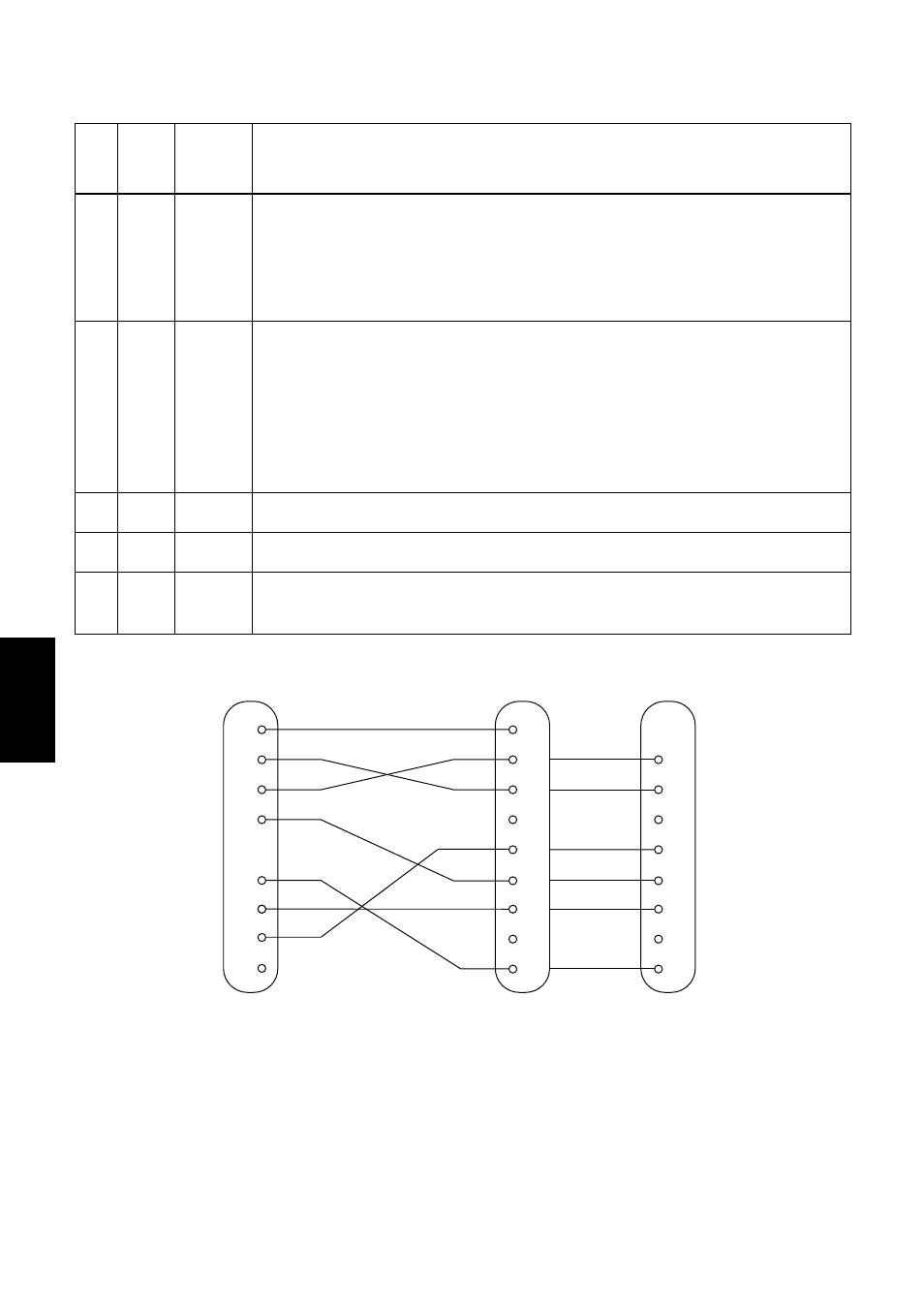
F-GND
TXD
RXD
RTS
DSR
20
25
7
S-GND
DTR
INIT
Printer side
(D-sub 25 pin)
IBM PC side
3
2
7
8
6
5
1
4
F-GND
TXD
RXD
RTS
CTS
DSR
S-GND
DCD
DTR
9 pin
25 pin
- LC-90 (131 pages)
- LC-240C (82 pages)
- MP500 Series (2 pages)
- Star SP317 (63 pages)
- SP200F (111 pages)
- NL-10 (35 pages)
- MP115MP-24G-A (42 pages)
- LC-6211 (60 pages)
- 800C (76 pages)
- SLIP SP298 (79 pages)
- LC-1021 (91 pages)
- SP200F SERIES (90 pages)
- SP200F SERIES (114 pages)
- 150 (151 pages)
- LC-1011C (88 pages)
- RS232 (80 pages)
- FUTUREPRINT TSP100 (32 pages)
- SP700 Series (2 pages)
- DP8340RC (40 pages)
- SP342F-A (62 pages)
- PR921-24-A (31 pages)
- SP312F (36 pages)
- SP300 Series (70 pages)
- SP317 (63 pages)
- SP2000 Series (147 pages)
- LC-8021 (86 pages)
- NP-325 (45 pages)
- DP8340 (59 pages)
- PW2000-24 (4 pages)
- HL 80825321 (176 pages)
- Line Thermal Printer (181 pages)
- PUNKT-MATRIX-DRUCKER LC-7211 (182 pages)
- Automatic Sheet Feeder SF-15HA (42 pages)
- Star futurePRNT TSP100GT (2 pages)
- Star SP200 Series (127 pages)
- PT-10Q (36 pages)
- SP298 Series (144 pages)
- LC-8521 (116 pages)
- RSR 28 (5 pages)
- SP320S (94 pages)
- Dot Impact Printer (104 pages)
- LC-4521 (191 pages)
- PT-10Y (32 pages)
- Line Thermal/Dot Printer (209 pages)
- ATAR LC-500 (72 pages)