Figure b-1 – Sun Microsystems Interface Adapter User Manual
Page 52
32
Sun PCI High Speed Quad Port Serial Interface Adapter User’s Guide • December 2005
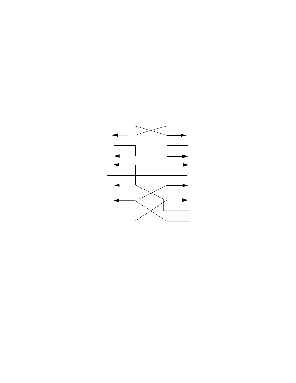
illustrates a synchronous null modem cable that enables you to connect
two Sun systems that each supply clocking, using the RS-449 interface. Each Sun
system supplies clocking on pins 17 and 35. The null modem cable routes this
clocking to pins 8 and 26 on the opposite side to provide receive clocking.
Because the RS-449 interface is balanced, there are two pins for each signal. For
example, Transmit Data (TxD), pins 4 and 22, is connected to Received Data (RxD),
pins 6 and 24. This means that pin 4 is connected to pin 6 and pin 22 is connected to
pin 24.
FIGURE B-1
Null Modem Cable –Both Sun Systems Supplies Clocking
TxD (4,22)
RxD (6,24)
RTS (7,25)
CTS (9,27)
DSR (11,29)
SG (19)
DCD (13,31)
RxC (8,26)
DTR (12,30)
TxC (17,35)
Sun workstation
TxD (4,22)
RxD (6,24)
RTS (7,25)
CTS (9,27)
DSR (11,29)
SG (19)
DCD (13,31)
RxC (8,26)
DTR (12,30)
TxC (17,35)
Sun workstation
- 6.0005E+11 (333 pages)
- SOLARIS 10 (121 pages)
- Sun Adapter TCP (150 pages)
- Sun Fire X4150 (150 pages)
- Sun StorageTek 5800 (136 pages)
- Virtual Tape Library (292 pages)
- eWay JDBC/ODBC Adapter (133 pages)
- LSI22320-SR (48 pages)
- Ethernet MMF/UTP Adapter (122 pages)
- SunSwift 600MP series (28 pages)
- 2.0 (60 pages)
- FASTETHERNET 6U (106 pages)
- Netra CP2500 (74 pages)
- 1.0 (182 pages)
- GigaSwift Ethernet Adapter (126 pages)
- SUN BLADE 150 (20 pages)
- X1150A (106 pages)
- Sun Quad (62 pages)
- VIRTUALBOX VERSION 3.1.0_BETA2 (283 pages)
- Ethernet PCI-X Adapter (78 pages)
- Sun StorageTek SG-XPCIE2FCGBE-E-Z (54 pages)
- SG-XPCIE2FC-EM8-Z (56 pages)
- STOREDGE A5000 (2 pages)
- THE SUN 805-7945-10 (24 pages)
- Sun FastEthernet PCI Adapter 805-1759-10 (38 pages)
- Sun Fire X4150 Server (80 pages)
- 805-1797-10 (65 pages)
- Sun StorEdge 5210 NAS (100 pages)
- Sun StorEdge A5000 (2 pages)
- StorEdge 3900 Series (162 pages)
- Sun PCI High Speed Quad Port Serial Interface Adapter 819-1207-11 (64 pages)
- Sun Fire X4200 M2 (50 pages)
- StreamLine SL8500 (200 pages)
- Sun StorEdge T3 (88 pages)
- TIMBERWOLF 9740 (100 pages)
- eWay SAP BAPI (123 pages)
- Ethernet PCI Adapter (10 pages)
- StorageTek L40 (92 pages)
- Smart Cards (14 pages)
- SUN STORAGETEK VSM GUI (68 pages)
- Gigabit Ethernet MMF/UTP Adapter (122 pages)
- Sun Fire X4100 M2 (50 pages)
- PCI (50 pages)
- StorageTek HP LTO4 (38 pages)
- Netra CP32x0 (66 pages)