6 connecting cables, Atx main pwr & cpu pwr connectors, X7sla-l/x7sla-h user's manual – SUPER MICRO Computer X7SLA-H User Manual
Page 36: Pin atx main pwr 4-pin external pwr a b, Optional) (required), Side view
2-16
X7SLA-L/X7SLA-H User's Manual
2-6 Connecting Cables
This section provides brief descriptions and pin-out definitions for onboard power
connectors. Be sure to use the correct cable for each header or connector.
24-Pin ATX Main PWR
4-Pin External PWR
A
B
ATX Power 24-pin Connector
Pin Definitions (JPW1)
Pin# Definition Pin # Definition
13
+3.3V
1
+3.3V
14
-12V
2
+3.3V
15
COM
3
COM
16
PS_ON
4
+5V
17
COM
5
COM
18
COM
6
+5V
19
COM
7
COM
20
Res (NC)
8
PWR_OK
21
+5V
9
5VSB
22
+5V
10
+12V
23
+5V
11
+12V
24
COM
12
+3.3V
(Optional)
(Required)
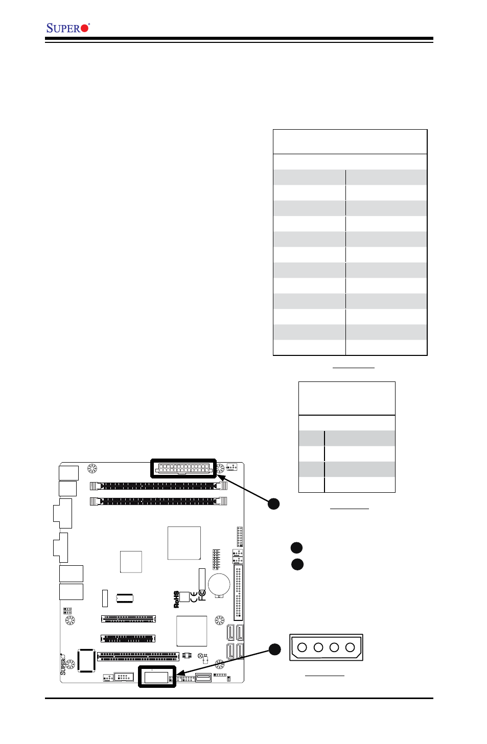
ATX Main PWR & CPU PWR
Connectors
The 24-pin main power connector
(JPW1) is used to provide power to
the motherboard. The 4-pin External
Power connector (JPW2) is optional for
peripheral devices. These power con-
nectors meet the SSI EPS 12V specifi-
cation. See the table on the right for pin
definitions of these connectors.
JF
1
J1
3
JL
1
R52
R53
JPL1
JPL2
FAN3
FAN1
FAN_NB
4
1
FAN2
J3
J5
1
J4
6
JP
5
JP
4
BT
1
JBT1
TP_ICH3
Te
st
ed
t
o
C
omply
W
ith FC
C
S
ta
n
d
ar
d
s
FOR HOME OR OFFICE USE
X7SLA-H
DESIGNED IN USA
NIC
I-SA
TA
3
I-SA
TA
2
I-SA
TA
1
I-SA
TA
0
SLOT7 PCI-E X4 in X8
SLOT6 PCI-E X8
USB2/3
COM2
USB4/5
USB6
JBT1:CMOS CLEAR
ID
E
SLOT5 PCI 33MHZ
1-2:ENABLE 2-3:DISABLE
JPL1-2:LAN1/2
INTRUSION
JL1:CHASSIS
LAN2
LAN1
VG
A
COM1
X
LED
PWR
HDD
NIC
/FF
OH
RS
T
PWR ON
1
JF1
DIMM1A
DIMM1B
JPW1
JPW2 for Device Power Only
KB/MOUSE
USB
7
USB0/1
CPU
945GC
ICH7R
B
A
External Power Connector
In addition to the 24-pin main power
connector, the 4-pin External Power con-
nector at JP3 is used to provide power
to external devices such as hard disks &
CD-ROM drives. This power connector
supports 12V and 5V devices.
4-Pin External Power
Connector
Pin Definitions
Pin Definition
1
+12V
2
Ground 1
3
Ground 2
4
+5V
Side View