Front control panel pin definitions, Chapter 2: installation, Jf1 header pins – SUPER MICRO Computer X7SLA-H User Manual
Page 33: Power led hdd led a b, Nic2 led led_anode
Chapter 2: Installation
2-13
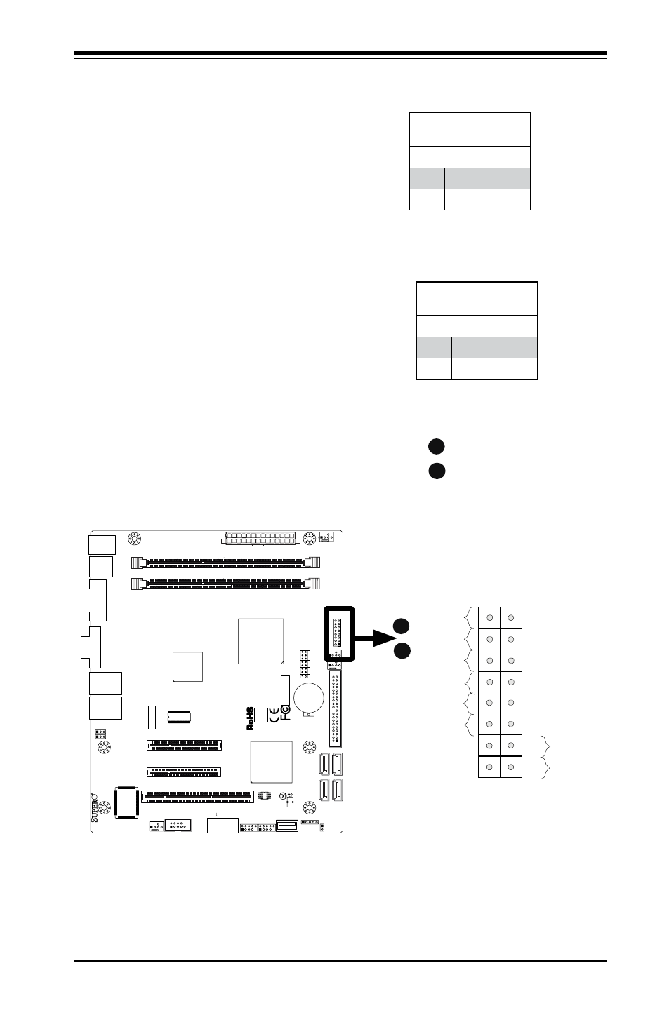
Front Control Panel Pin Definitions
Power LED
The Power LED connection is located
on pins 15 and 16 of JF1. Refer to the
table on the right for pin definitions.
Power LED
Pin Definitions (JF1)
Pin# Definition
15
+3.3V
16
Ground
POWER LED
HDD LED
A
B
JF
1
J1
3
JL
1
R52
R53
JPL1
JPL2
FAN3
FAN1
FAN_NB
4
1
FAN2
J3
J5
1
J4
6
JP
5
JP
4
BT
1
JBT1
TP_ICH3
Te
st
ed
t
o
C
omply
W
ith FC
C
S
ta
n
d
ar
d
s
FOR HOME OR OFFICE USE
X7SLA-H
DESIGNED IN USA
NIC
I-SA
TA
3
I-SA
TA
2
I-SA
TA
1
I-SA
TA
0
SLOT7 PCI-E X4 in X8
SLOT6 PCI-E X8
USB2/3
COM2
USB4/5
USB6
JBT1:CMOS CLEAR
ID
E
SLOT5 PCI 33MHZ
1-2:ENABLE 2-3:DISABLE
JPL1-2:LAN1/2
INTRUSION
JL1:CHASSIS
LAN2
LAN1
VG
A
COM1
X
LED
PWR
HDD
NIC
/FF
OH
RS
T
PWR ON
1
JF1
DIMM1A
DIMM1B
JPW1
JPW2 for Device Power Only
KB/MOUSE
USB
7
USB0/1
CPU
945GC
ICH7R
Power Button
OH/Fan Fail LED
1
NIC1 LED
Reset Button
2
HDD LED
Power LED
Reset
PWR
LED_Anode+
LED_Anode+
LED_Anode+
LED_Anode+
Ground
Ground
X
X
NIC2 LED
LED_Anode+
A
HDD LED
The HDD LED connection is located
on pins 13 and 14 of JF1. Attach a
hard drive LED cable here to display
disk activity (for any hard drive ac-
tivities on the system, including Serial
ATA and IDE). See the table on the
right for pin definitions.
HDD LED
Pin Definitions (JF1)
Pin# Definition
13
+3.3V
14
HD Active
B
JF1 Header Pins