X7sla-l/x7sla-h user's manual, Jf1 header pins, Nic1 led nic2 led oh/fan fail led – SUPER MICRO Computer X7SLA-H User Manual
Page 34: Nic2 led led_anode
2-14
X7SLA-L/X7SLA-H User's Manual
Power Button
OH/Fan Fail LED
1
NIC1 LED
Reset Button
2
HDD LED
Power LED
Reset
PWR
LED_Anode+
LED_Anode+
LED_Anode+
LED_Anode+
Ground
Ground
X
X
NIC2 LED
LED_Anode+
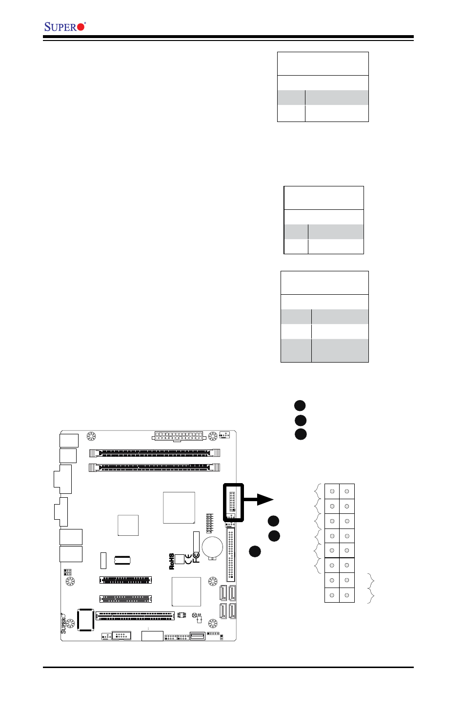
NIC1/NIC2 LED Indicators
The NIC (Network Interface Controller
or Ethernet Controller) LED connec-
tion for LAN port 1 is located on pins
11 and 12 of JF1, and the LED con-
nection for LAN Port 2 is on Pins 9
and 10. Attach the NIC LED cables to
display network activity. Refer to the
table on the right for pin definitions.
GLAN1/2 LED
Pin Definitions (JF1)
Pin# Definition
9/11
Vcc
10/12
Ground
NIC1 LED
NIC2 LED
OH/Fan Fail LED
Overheat (OH)/Fan Fail LED
Connect an LED Cable to the OH/
Fan Fail connection on pins 7 and 8
of JF1 to provide advanced warnings
of chassis overheat or fan failure.
Refer to the table on the right for pin
definitions.
OH/Fan Fail LED
Pin Definitions (JF1)
Pin# Definition
7
Vcc
8
Ground
OH/Fan Fail Indicator
Status
State Definition
Off
Normal
On
Overheat
Flash-
ing
Fan Fail
A
JF
1
J1
3
JL
1
R52
R53
JPL1
JPL2
FAN3
FAN1
FAN_NB
4
1
FAN2
J3
J5
1
J4
6
JP
5
JP
4
BT
1
JBT1
TP_ICH3
Te
st
ed
t
o
C
omply
W
ith FC
C
S
ta
n
d
ar
d
s
FOR HOME OR OFFICE USE
X7SLA-H
DESIGNED IN USA
NIC
I-SA
TA
3
I-SA
TA
2
I-SA
TA
1
I-SA
TA
0
SLOT7 PCI-E X4 in X8
SLOT6 PCI-E X8
USB2/3
COM2
USB4/5
USB6
JBT1:CMOS CLEAR
ID
E
SLOT5 PCI 33MHZ
1-2:ENABLE 2-3:DISABLE
JPL1-2:LAN1/2
INTRUSION
JL1:CHASSIS
LAN2
LAN1
VG
A
COM1
X
LED
PWR
HDD
NIC
/FF
OH
RS
T
PWR ON
1
JF1
DIMM1A
DIMM1B
JPW1
JPW2 for Device Power Only
KB/MOUSE
USB
7
USB0/1
CPU
945GC
ICH7R
B
JF1 Header Pins
A
B
C
C