Back panel connectors, X7sla-l/x7sla-h user's manual – SUPER MICRO Computer X7SLA-H User Manual
Page 28
2-8
X7SLA-L/X7SLA-H User's Manual
Backpanel USB 0
Backpanel USB 1
Internal USB 2/3
Internal USB 4/5
Front Panel USB 6
Internal USB 7 (Type A)
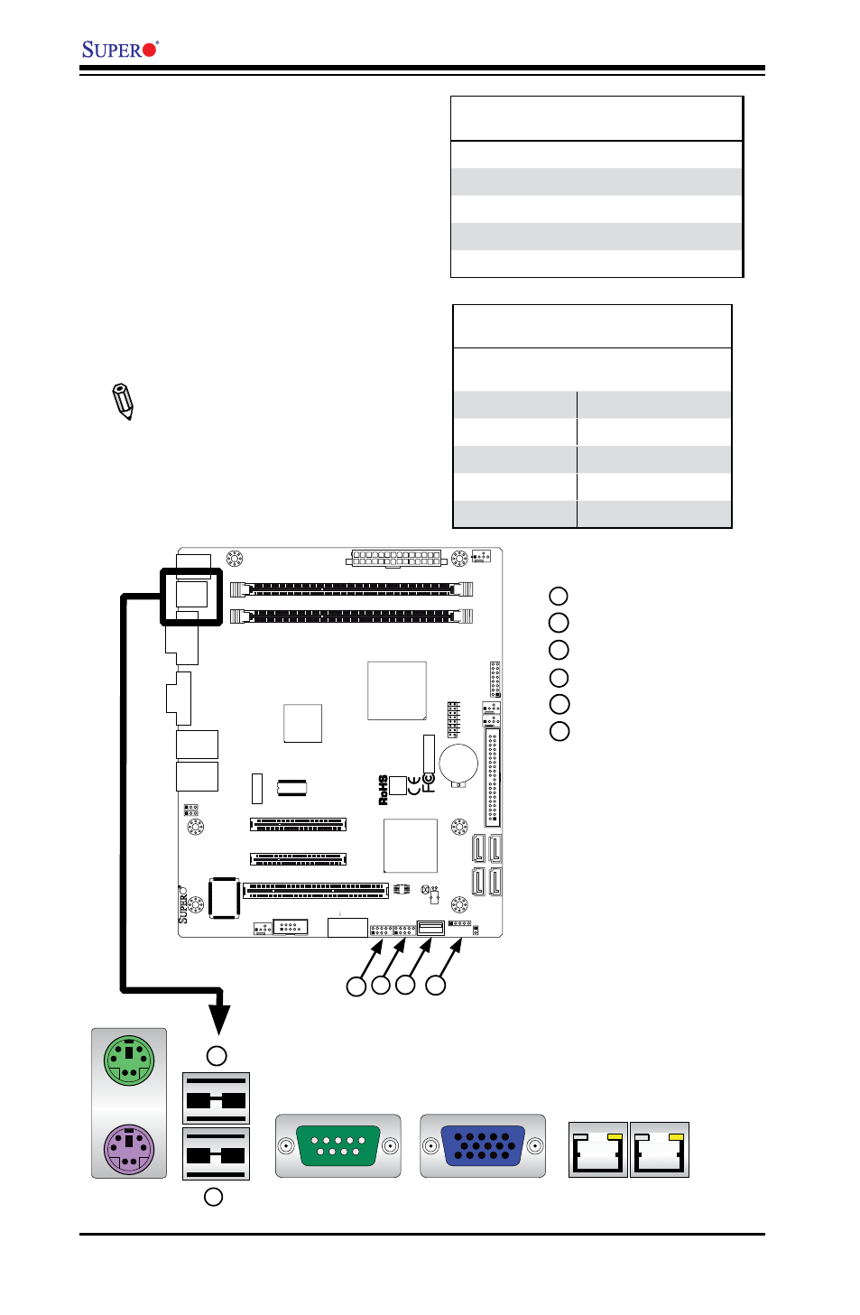
Universal Serial Bus (USB)
Two Universal Serial Bus ports (USB
0 and USB 1) are located on the I/O
backplane. Additionally, one Type A
Internal USB headers (USB 7) and
five USB connections (USB 2/3, 4/5,
6) are also located on the mother-
board to provide front chassis access.
(Cables are not included). See the
tables on the right for pin definitions.
Note: USB 7 (Type A) is available
only on the X7SLA-H mother-
board.
Back Panel USB 0/1
Pin Definitions
Pin# Definition Pin# Definition
1
+5V
5
+5V
2
USB_PN
6
USB_PN
3
USB_PP
7
USB_PP
4
Ground
8
Ground
Front Panel USB 2/3/4/5
Pin Definitions
USB 2, 4
Pin # Definition
USB 3, 5, 6
Pin # Definition
1
+5V
6
+5V
2
USB_PN2
7
USB_PN3
3
USB_PP2
8
USB_PP3
4
Ground
9
Ground
5
NA
10
Key
4
3
1
2
6
5
1
2
JF
1
J1
3
JL
1
R52
R53
JPL1
JPL2
FAN3
FAN1
FAN_NB
4
1
FAN2
J3
J5
1
J4
6
JP
5
JP
4
BT
1
JBT1
TP_ICH3
Te
st
ed
t
o
C
omply
W
ith FC
C
S
ta
n
d
ar
d
s
FOR HOME OR OFFICE USE
X7SLA-H
DESIGNED IN USA
NIC
I-SA
TA
3
I-SA
TA
2
I-SA
TA
1
I-SA
TA
0
SLOT7 PCI-E X4 in X8
SLOT6 PCI-E X8
USB2/3
COM2
USB4/5
USB6
JBT1:CMOS CLEAR
ID
E
SLOT5 PCI 33MHZ
1-2:ENABLE 2-3:DISABLE
JPL1-2:LAN1/2
INTRUSION
JL1:CHASSIS
LAN2
LAN1
VG
A
COM1
X
LED
PWR
HDD
NIC
/FF
OH
RS
T
PWR ON
1
JF1
DIMM1A
DIMM1B
JPW1
JPW2 for Device Power Only
KB/MOUSE
USB
7
USB0/1
CPU
945GC
ICH7R
Back Panel Connectors
4
3
6 5