Back panel connectors, Chapter 2: installation, Backpanel) com1 com2 (x7sla-h only) – SUPER MICRO Computer X7SLA-H User Manual
Page 29
Chapter 2: Installation
2-9
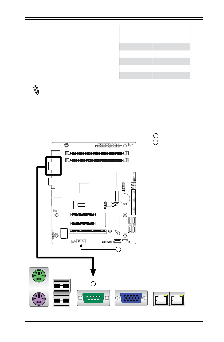
Serial Ports
Two COM connections (COM1 & COM2)
are located on the motherboard. COM1
is located on the Backplane I/O panel.
COM2 is located below the Super I/O
chip to provide additional onboard se-
rial connection support. See the table
on the right for pin definitions.
Note: COM2 is available only on
the X7SLA-H motherboard.
Serial Ports-COM1/COM2
Pin Definitions
Pin # Definition
Pin # Definition
1
DCD
6
DSR
2
RXD
7
RTS
3
TXD
8
CTS
4
DTR
9
RI
5
Ground
10
N/A
(Backpanel) COM1
COM2 (X7SLA-H only)
1
2
1
2
JF
1
J1
3
JL
1
R52
R53
JPL1
JPL2
FAN3
FAN1
FAN_NB
4
1
FAN2
J3
J5
1
J4
6
JP
5
JP
4
BT
1
JBT1
TP_ICH3
Te
st
ed
t
o
C
omply
W
ith FC
C
S
ta
n
d
ar
d
s
FOR HOME OR OFFICE USE
X7SLA-H
DESIGNED IN USA
NIC
I-SA
TA
3
I-SA
TA
2
I-SA
TA
1
I-SA
TA
0
SLOT7 PCI-E X4 in X8
SLOT6 PCI-E X8
USB2/3
COM2
USB4/5
USB6
JBT1:CMOS CLEAR
ID
E
SLOT5 PCI 33MHZ
1-2:ENABLE 2-3:DISABLE
JPL1-2:LAN1/2
INTRUSION
JL1:CHASSIS
LAN2
LAN1
VG
A
COM1
X
LED
PWR
HDD
NIC
/FF
OH
RS
T
PWR ON
1
JF1
DIMM1A
DIMM1B
JPW1
JPW2 for Device Power Only
KB/MOUSE
USB
7
USB0/1
CPU
945GC
ICH7R
Back Panel Connectors