5 connectors/i/o ports, Back panel connectors and i/o ports, Back panel connectors – SUPER MICRO Computer X7SLA-H User Manual
Page 26
2-6
X7SLA-L/X7SLA-H User's Manual
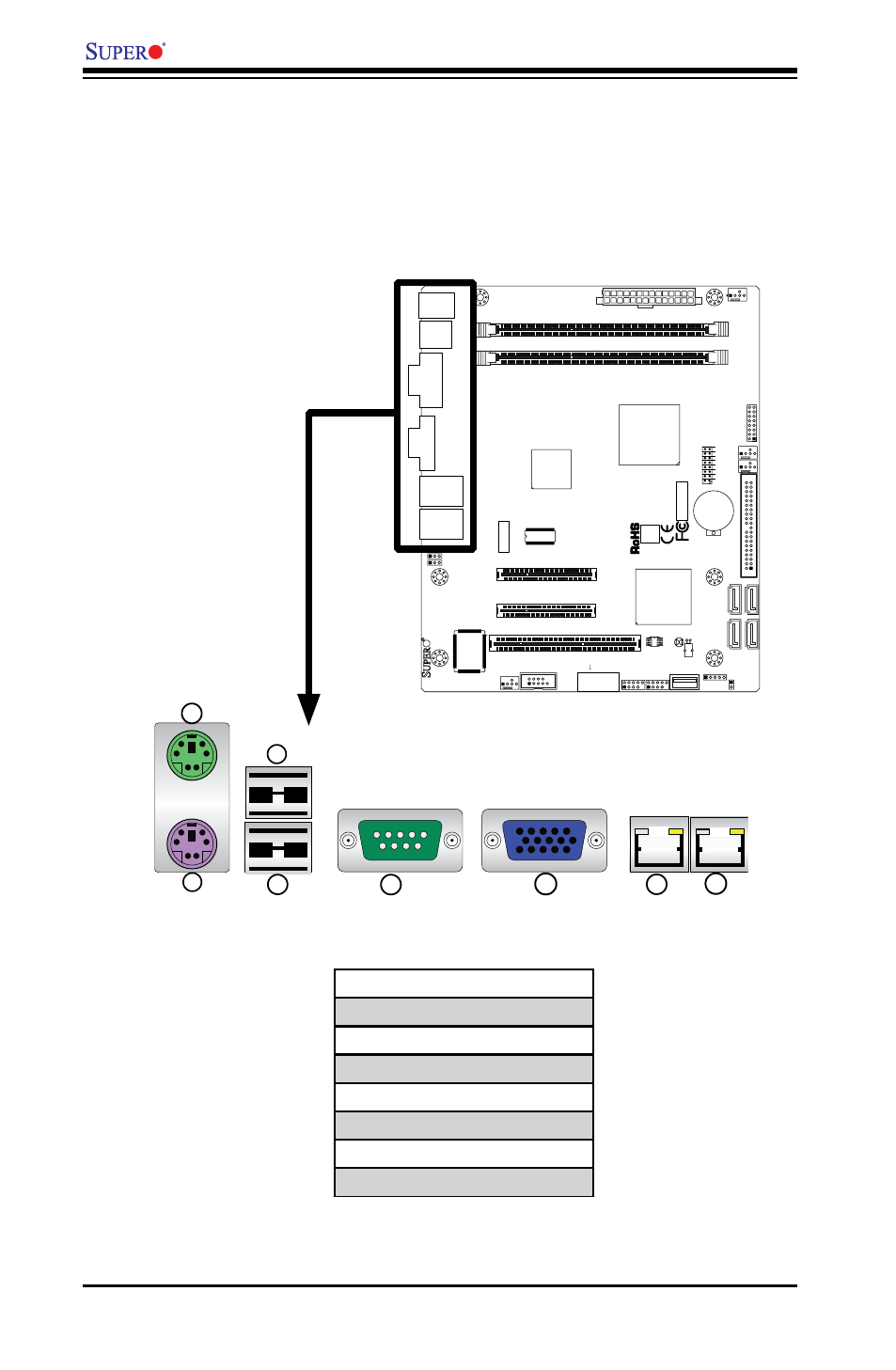
I/O Port Locations and Definitions
2-5 Connectors/I/O Ports
The I/O ports are color coded in conformance with the PC 99 specification. See the
figure below for the colors and locations of the various I/O ports.
Back Panel Connectors and I/O Ports
2
4
7
1
3
5
6
8
1. Keyboard (Purple)
2. PS/2 Mouse (Green)
3. USB Port 0
4. USB Port 1
5. COM 1 (Green)
6. VGA (Blue)
7. LAN1
8. LAN 2 (X7SLA-H only)
JF
1
J1
3
JL
1
R52
R53
JPL1
JPL2
FAN3
FAN1
FAN_NB
4
1
FAN2
J3
J5
1
J4
6
JP
5
JP
4
BT
1
JBT1
TP_ICH3
Te
st
ed
t
o
C
omply
W
ith FC
C
S
ta
n
d
ar
d
s
FOR HOME OR OFFICE USE
X7SLA-H
DESIGNED IN USA
NIC
I-SA
TA
3
I-SA
TA
2
I-SA
TA
1
I-SA
TA
0
SLOT7 PCI-E X4 in X8
SLOT6 PCI-E X8
USB2/3
COM2
USB4/5
USB6
JBT1:CMOS CLEAR
ID
E
SLOT5 PCI 33MHZ
1-2:ENABLE 2-3:DISABLE
JPL1-2:LAN1/2
INTRUSION
JL1:CHASSIS
LAN2
LAN1
VG
A
COM1
X
LED
PWR
HDD
NIC
/FF
OH
RS
T
PWR ON
1
JF1
DIMM1A
DIMM1B
JPW1
JPW2 for Device Power Only
KB/MOUSE
USB
7
USB0/1
CPU
945GC
ICH7R
Back Panel Connectors