Appendix a: serial interface, A-1. connectors and signals, Rs-232c – Star Micronics SP200F SERIES User Manual
Page 90: Rs-422a
– 87 –
APPENDIX
Appendix A: Serial Interface
A-1. Connectors and Signals
RS-232C
Pin no.
Signal name
I/O direction
Function
1
F-GND
—
Frame ground
2
N/C
Not connected
3
RXD
IN
Received data
4
RTS
OUT
Data transmission request signal. This is always
“SPACE” when the printer is turned on. (Always
“SPACE” status)
5-6
N/C
Not connected
7
S-GND
—
Signal ground
8-10
N/C
Not connected
11
RCH
OUT
When the printer is ready to receive data, the signal line
is same as pin 20.
12
N/C
Not connected
13
GND
—
Signal ground
14
FAULT
OUT
When printer error occurs (such as paper out, mechani-
cal error, etc.) this signal changes to “MARK”.
15-19
N/C
Not connected
20
DTR
OUT
Data terminal ready signal. When the printer is ready to
receive data, this signal changes to “SPACE”.
21-25
N/C
Not connected
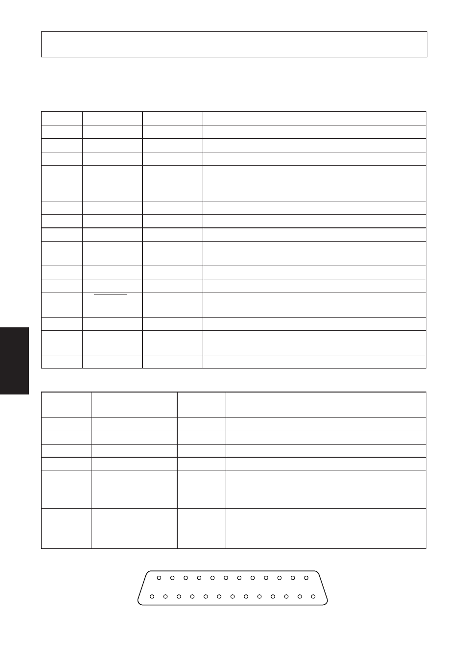
Fig. A-1 Serial interface connector
RS-422A
Pin no.
Signal name
I/O
Function
direction
9
SD (+)
OUT
Transmitted data
10
SD (–)
OUT
Transmitted data
17
RD (+)
IN
Received data
18
RD (–)
IN
Received data
24
RS (+)
OUT
Data transmission request signal. When the
printer is ready to receive data, this signal
changes to “SPACE”.
25
RS (–)
OUT
Data transmission request signal. When the
printer is ready to receive data, this signal
changes to “SPACE”.
14
1
13
25