Installation, Step: 1 mains connection, Step: 2 connections – Sanyo CE42LH2WP User Manual
Page 31: English
11
English
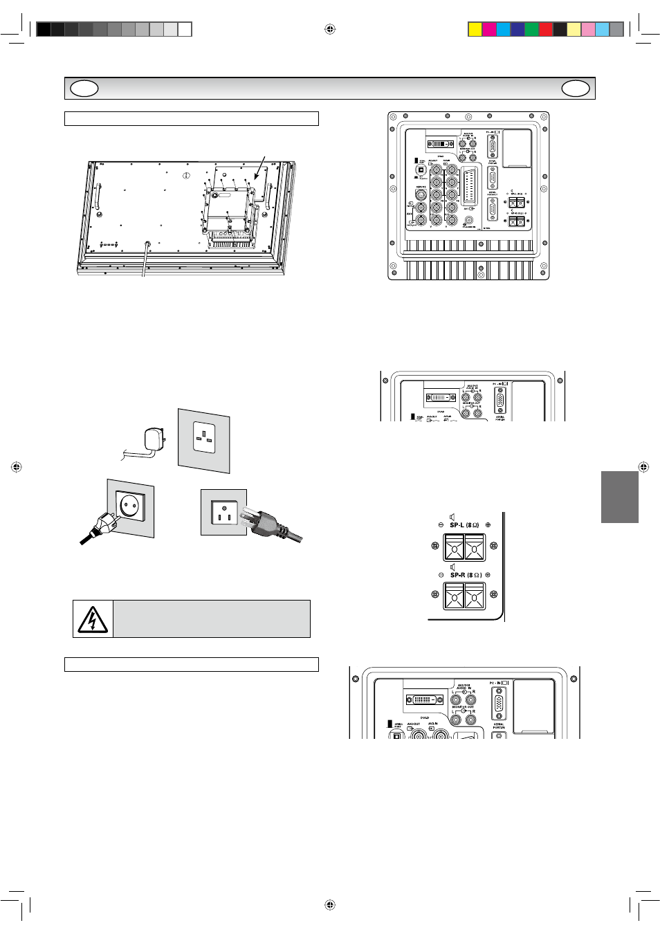
Step: 1 Mains Connection
N&RQQHFWWKHGLVSOD\XQLWWR9*$%1&DQG6FDUWFRQ-
nector as required.
1. Connect the in-line power connector to the Mains Inlet as shown
above.
2. Connect the power cord of the LCD monitor to a suitable wall
outlet.
As this product does not have a mains On/Off switch, please
ensure your mains plug is easily accessible.
The LCD monitor is prepared for a mains voltage AC100 ~ 240V,
+]+]7RFRPSOHWHO\VZLWFKRIIWKHPDLQVRUZKHQWKH
GLVSOD\XQLWLVQRWWREHXVHGIRUDQH[WHQGHGSHULRGRIWLPHLWLV
advisable to disconnect the power cord from the power outlet.
Please use the correct mains lead supplied with the set for your
area.
3. Warning: To prevent injury, the unit must be securely attached to
the wall in accordance with the installation instructions.
WARNING!
High voltages are used in the
RSHUDWLRQRIWKLVVHW5HIHUVHUYLFHWRTXDOLÀHG
service personnel.
Step: 2 Connections
N
To switch either AV1, RGB, AV2, AV3, PC, DVI or Network by pressing
the INPUT button on your remote control repeatedly.
1. AV1
SCART connection/CVBS/RGB/S-VIDEO.
2. RGB
TTL input (5V RGB signals) into SCART terminal.
<3E3U5*%+9FRQQHFWLRQ$9
Choose Y, Pb, Pr or RGB H/V connection by selecting AV2 Setting
in Set up menu (refer to the INSTRUCTION MANUAL on page 10).
You can connect your DVD player to the Y, Pb, Pr terminals instead
RIXVLQJDVFDUWOHDG7KLVFDQVXSSRUWKLJKGHÀQLWLRQLQDQDORJXH
component form. RGB H/V can be used as a PC input via the BNC
terminals. Both options support a large range of resolutions (refer
to the INSTRUCTION MANUAL on page 17). AV2-OUT can be used
to output the incoming AV2 signal to the other monitor.
4. AV3
Composite (CVBS) signal input.
AV3-OUT can be used to output the incoming AV3 signal to the
other monitor.
5. DVI-D (Digital Video Interface)
DVI-D supports a large range of resolutions as shown in the IN-
STRUCTION MANUAL on page 17.
6. PC connection
PC input (PC-IN D-SUB). This input supports a large range of reso-
lutions as shown in the INSTRUCTION MANUAL page 17. Audio
can be connected via the 3.5mm PC-AUDIO IN.
7. External Speaker
Output the audio signal from AV1, AV2, AV3, PC and DVI.
The speaker impedance is 8 ohms.
8. AV2 / DVI AUDIO IN
Connect the audio output (stereo) from a computer or video equip-
ment connected AV2 or DVI.
9. Monitor Audio OUT
7KLVWHUPLQDOVRXWSXWÀ[HGOHYHOIURP$8',2,1
10. RS232C IN/OUT
When the monitor is controlled by a computer, connect to this jack
with serial control cable.
You can connect to another monitor with RS232C OUT.
:KHQ\RXFRQQHFW3&ZLWK56&VHOHFW´21µDW1HWZRUN
standby in Installation mode.
,ILWLVVHOHFWHG´2))µ56&WHUPLQDOVGRQRWIXQFWLRQDO$OVR
VHOHFWSXVKEXWWRQWR´6(5,$/32$57µ
INSTALLATION
AC Mains
Outlet
7KLVÀJXUHLVLQFKPRGHO
LD-Net
GB
GB