4 i/o ports – SUPER MICRO Computer 6014P-TR User Manual
Page 41
Chapter 5: Advanced Serverboard Setup
5-7
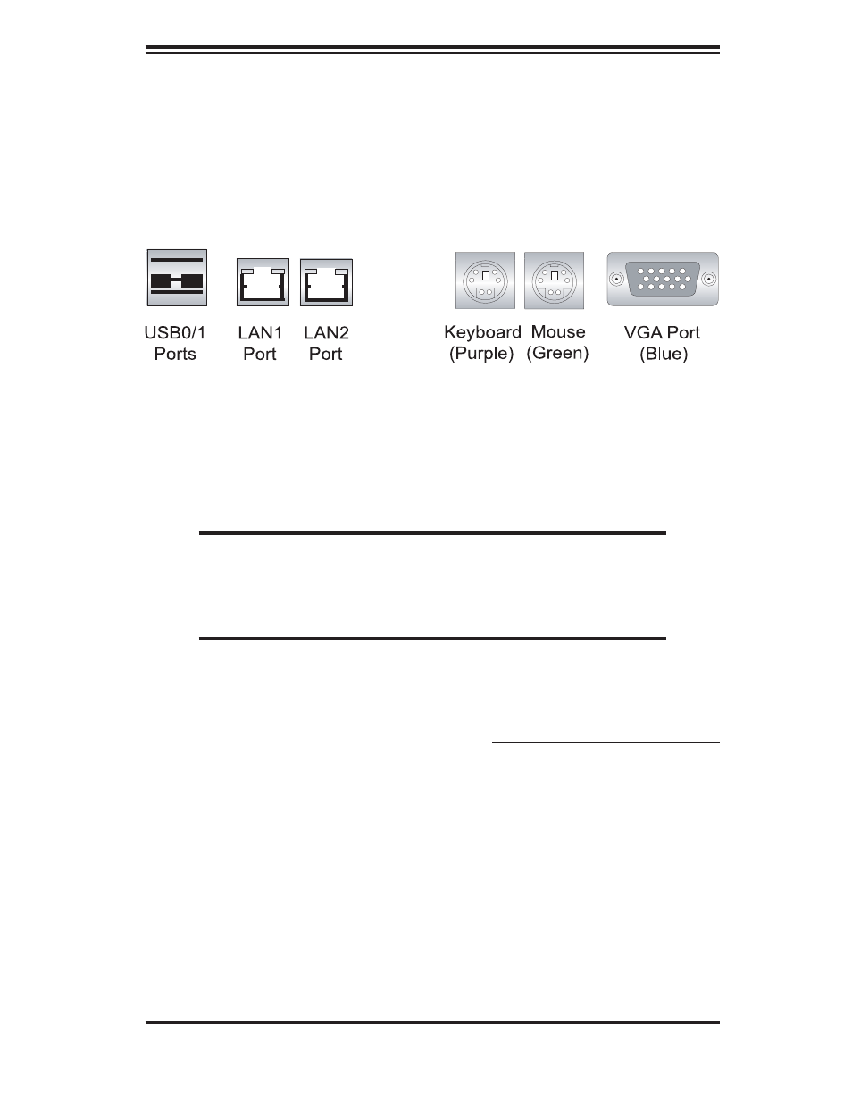
5-4 I/O
Ports
The I/O ports are color coded in conformance with the PC 99 specifi cation. See
Figure 5-4 below for the colors and locations of the various I/O ports.
Figure 5-4. I/O Ports
5-5 Installing
Memory
Note: Check the Supermicro web site for recommended memory modules: http://
www.supermicro.com/support/resources/
CAUTION
Exercise extreme care when installing or removing DIMM modules
to prevent any possible damage. Also note that the memory is inter-
leaved to improve performance (see step 1).
DIMM Installation (Figures 5-5a and 5-5b)
1. Insert the desired number of DIMMs into the memory sockets, starting with Bank
1. The memory scheme is interleaved so you must install two modules at a
time, beginning with DIMM #1A, then DIMM #1B, and so on.
2. Insert each DIMM module vertically into its socket. Pay attention to the notch
along the bottom of the module to prevent inserting the DIMM module incor-
rectly.
3. Gently press down on the DIMM module until it snaps into place in the sockets.
Repeat for all modules (see step 1 above).
Memory Support
The X6DHP-TG has six 184-pin DIMM slots that can support up to 12 GB of regis-
tered ECC DDR333 (PC2700) or up to 24 GB of registered ECC DDR266 (PC2100)
SDRAM. The serverboard was designed to support 2 GB modules in each socket,
but has only been verifi ed for up to 1 GB modules. The memory is an interleaved