Juniper Networks IDP SERIES IDP250 User Manual
Page 23
appliance is turned on and available, it sends a reset signal to the traffic interface timer
so that it does not reach the bypass trigger point. If the IDP OS encounters failure, then
it fails to send the reset signal, the timer counts down to the trigger point, and the traffic
interfaces enter a bypass state. If the IDP Series appliance is shut down gracefully, the
traffic interfaces immediately enter bypass.
With copper NICs, the bypass mechanism joins the interfaces mechanically to form a
circuit that bypasses IDP processing. Packets traverse the IDP Series device as if the path
from eth2 (receiving interface) to eth3 (transmiting interface) were a crossover cable.
No packet inspection or processing occurs.
With fiber NICs, the bypass mechanism uses use optical relays instead of copper relays.
During normal operations, the optical relays send light to the built-in optical transceivers.
When bypass is triggered, the relays flip state, and the light signal is redirected to optically
connect the two external ports.
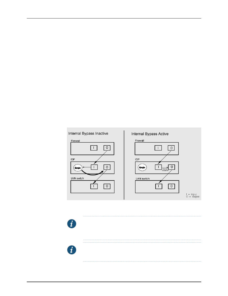
compares the data path when Internal Bypass is enabled but not
activated with the data path when Internal Bypass is activated.
Figure 6: Internal Bypass
When the IDP OS resumes healthy operations, it sends a reset signal to the traffic
interfaces, and the interfaces resume normal operation.
NOTE:
All copper port traffic interfaces support internal bypass. Some, but
not all, fiber port traffic interfaces support internal bypass. Check with your
sales contact for applicable part numbers.
NOTE:
Bypass settings are applicable only for deployments where the virtual
router is in the network path—transparent mode deployments.
11
Copyright © 2012, Juniper Networks, Inc.
Chapter 1: Hardware Overview