Figure 31: ethernet cable connector – Juniper Networks EX2200 User Manual
Page 96
•
Management Port Connector Pinout Information for an EX4500 Switch
•
Management Port Connector Pinout Information for an EX8200 Switch
•
Management Port Connector Pinout Information for an XRE200 External Routing
Engine
•
Cables Connecting the EX8200 Switch to Management Devices
Connecting an EX Series Switch to a Management Console
This topic applies to multiple hardware devices in the EX Series product family, which
includes switches and the XRE200 External Routing Engine.
You can configure and manage these devices using a dedicated console. Every device
has a console port with an RJ-45 connector. Use the console port to connect the device
to the management console or to a console server. The console port accepts a cable
with an RJ-45 connector.
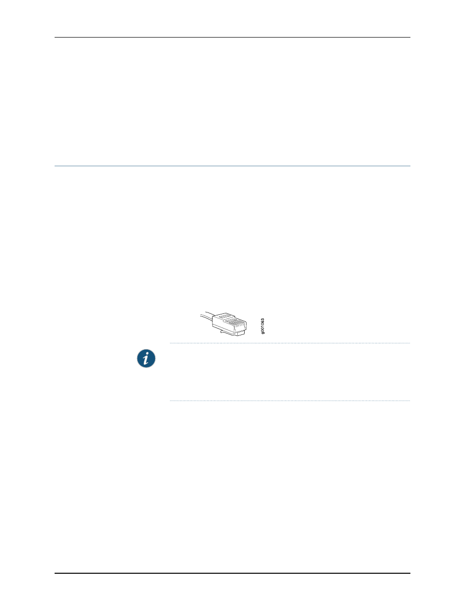
Ensure that you have an Ethernet cable with an RJ-45 connector available. An RJ-45
cable and an RJ-45 to DB-9 serial port adapter are supplied with the device.
Figure 31 on page 76 shows the RJ-45 connector of the Ethernet cable supplied with the
device.
Figure 31: Ethernet Cable Connector
NOTE: If your laptop or PC does not have a DB-9 male connector pin and you
want to connect your laptop or PC directly to the device, use a combination
of the RJ-45 to DB-9 female adapter supplied with the device and a USB to
DB-9 male adapter. You must provide the USB to DB-9 male adapter.
To connect the device to a management console (see Figure 32 on page 77 and Figure
33 on page 77):
1.
Connect one end of the Ethernet cable into the console port (labeled
CON
or
CONSOLE
) on the device.
For the location of the
CON/CONSOLE
port on different devices:
•
See “Rear Panel of an EX2200 Switch” on page 6.
•
See Rear Panel of an EX3200 Switch.
•
See Rear Panel of an EX4200 Switch.
•
See Front Panel of an EX4500 Switch.
•
See Switch Fabric and Routing Engine (SRE) Module in an EX8208 Switch.
Copyright © 2010, Juniper Networks, Inc.
76
Complete Hardware Guide for EX2200 Ethernet Switches