Juniper Networks EX2200 User Manual
Page 75
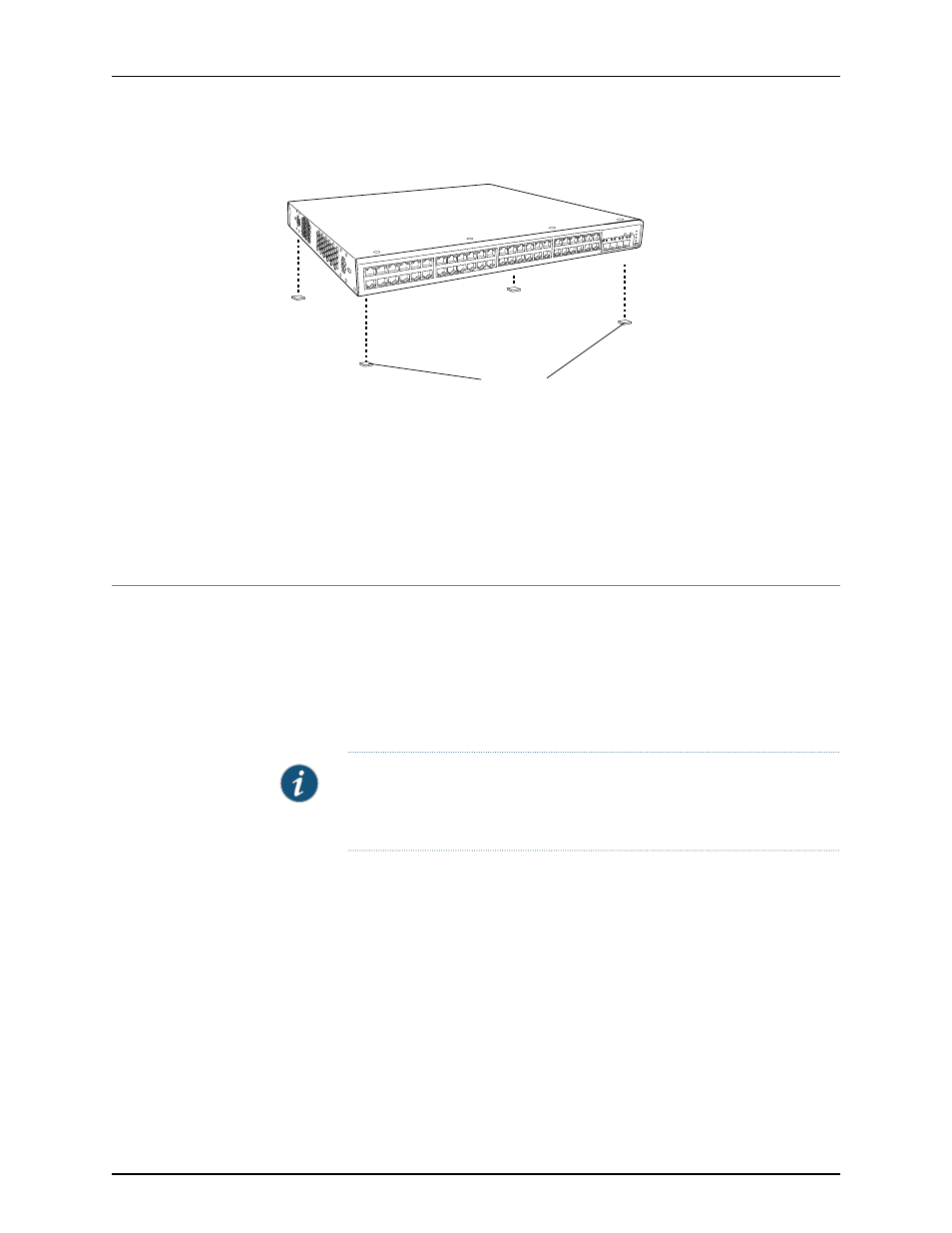
Figure 14: Attaching Rubber Feet to a Switch Chassis
Rubber feet
g027015
SYS
ALM
SPD
DX
POE
EN
Related
Documentation
Connecting AC Power to an EX2200 Switch on page 73
•
•
Connecting and Configuring an EX Series Switch (CLI Procedure) on page 87
•
Connecting and Configuring an EX Series Switch (J-Web Procedure) on page 89
•
Clearance Requirements for Airflow and Hardware Maintenance for EX2200 Switches
on page 42
Mounting an EX2200 Switch on Two Posts in a Rack or Cabinet
You can mount the switch on two posts of a 19-in. rack or cabinet by using the mounting
brackets provided with the switch. (The remainder of this topic uses “rack” to mean “rack
or cabinet”.)
You can mount the switch on four posts of a four-post rack by using the mounting brackets
provided with the separately orderable four-post rack-mount kit. See “Mounting an
EX2200 Switch on Four Posts in a Rack or Cabinet” on page 57.
NOTE: If you need to mount the switch in a recessed position on either a
two-post rack or a four-post rack, you can use the 2-in.-recess front mount
brackets provided in the separately orderable four-post rack-mount kit.
Before mounting the switch on two posts in a rack:
•
Verify that the site meets the requirements described in “Site Preparation Checklist
for EX2200 Switches” on page 33.
•
Place the rack in its permanent location, allowing adequate clearance for airflow and
maintenance, and secure it to the building structure.
•
Read “General Safety Guidelines and Warnings for EX Series Switches” on page 113,
with particular attention to “Chassis Lifting Guidelines for EX2200 Switches” on page 128.
•
Remove the switch from the shipping carton (see “Unpacking an EX2200 Switch” on
page 52).
Ensure that you have the following parts and tools available:
55
Copyright © 2010, Juniper Networks, Inc.
Chapter 8: Installing the Switch