Chapter 2: component descriptions, Chassis status leds in ex2200 switches, Chapter 2 – Juniper Networks EX2200 User Manual
Page 31: Component descriptions, Figure 4: chassis status leds in an ex2200 switch, Table 4: chassis status leds in an ex2200 switch
CHAPTER 2
Component Descriptions
•
Chassis Status LEDs in EX2200 Switches on page 11
•
Network Port and Uplink Port LEDs in EX2200 Switches on page 12
•
Management Port LEDs in EX2200 Switches on page 14
•
Power Supply in EX2200 Switches on page 14
•
Cooling System and Airflow in an EX2200 Switch on page 15
Chassis Status LEDs in EX2200 Switches
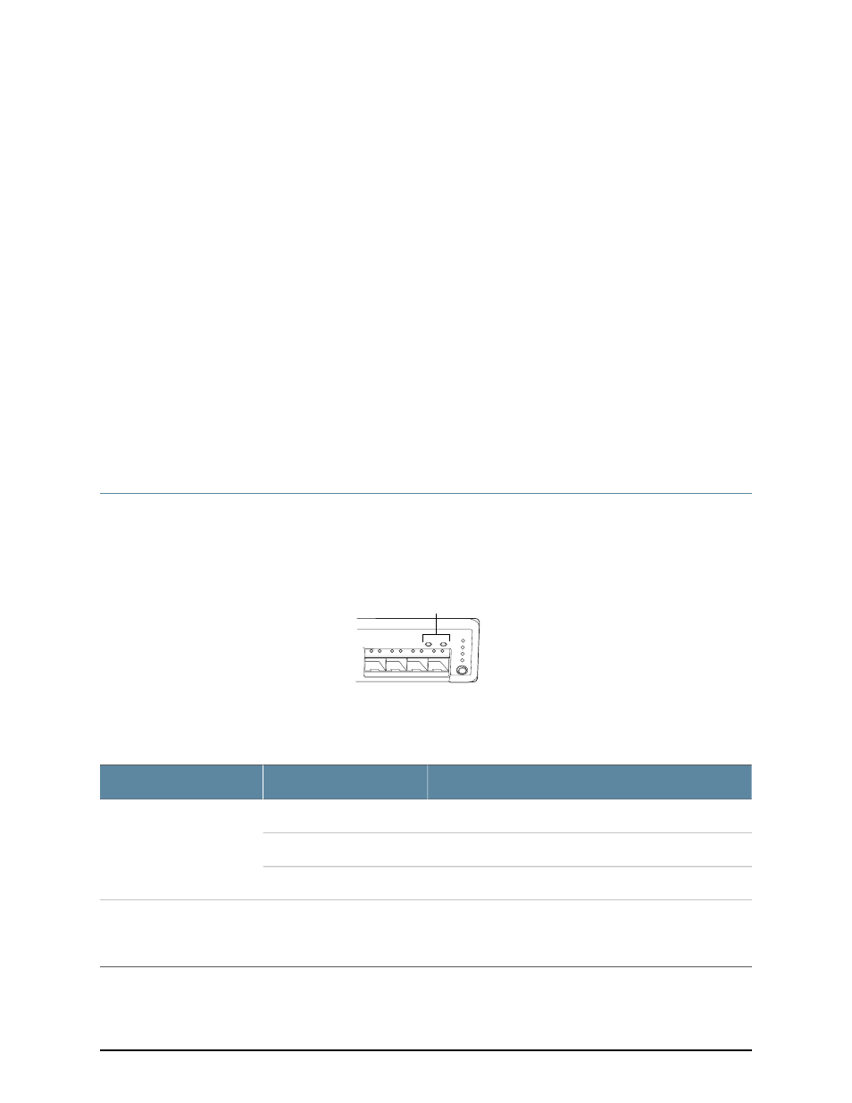
The front panel of an EX2200 switch has two chassis status LEDs labeled SYS and ALM
on the far right side of the panel, above the uplink ports (see Figure 4 on page 11).
Figure 4: Chassis Status LEDs in an EX2200 Switch
g027003
0
1
2
SYS
ALM
SPD
DX
EN
POE
3
Chassis
status LEDs
Table 4 on page 11 describes the chassis status LEDs in an EX2200 switch, their colors
and states, and the status they indicate.
Table 4: Chassis Status LEDs in an EX2200 Switch
State and Description
Color
LED Label
There is no alarm.
Unlit
ALM
There is a minor alarm.
Amber
There is a major alarm.
Red
•
On steadily—The switch is functioning normally.
•
Blinking—The switch is booting.
•
Off—The switch is off.
Green
SYS
A major alarm (red) indicates a critical error condition that requires immediate action.
11
Copyright © 2010, Juniper Networks, Inc.