2 signal descriptions, Signal descriptions, Itanium – Intel Itanium 2 Processor User Manual
Page 16
16
Datasheet
Electrical Specifications
..
All system bus outputs should be treated as open drain signals and require a high level source
provided by the V
CTERM
supply.
AGTL+ inputs have differential input buffers which use V
REF
as a reference level. AGTL+ output
signals require termination to V
CTERM
. In this document, “AGTL+ Input Signals” refers to the
AGTL+ input group as well as the AGTL+ I/O group when receiving. Similarly, “AGTL+ Output
Signals” refers to the AGTL+ output group as well as the AGTL+ I/O group when driving.
The Power Good (PWRGOOD) signal and Test Access Port (TAP) connection input signals use a
non-differential receiver with levels that are similar to AGTL+. No reference voltage is required for
these signals. The TAP Connection Output signals are AGTL+ output signals.
The Itanium 2 processor system bus requires termination on both ends of the bus. The Itanium 2
processor system bus supports both on-die and off-die termination controlled by two pins, TERMA
and TERMB. Please see the TERMA and TERMB pin description in
The HSTL clock signals are the differential clock inputs for the Itanium 2 processor. The SMBus
signals and LVTTL power pod signals are driven using the 3.3 V CMOS logic levels listed in
, respectively.
2.2.2
Signal Descriptions
Appendix A, “Signals Reference”
contains functional descriptions of all system bus signals and
LVTTL power pod signals. Further descriptions of the system management signals are contained in
. The signals listed under the “Power” and “Other” group are described here:
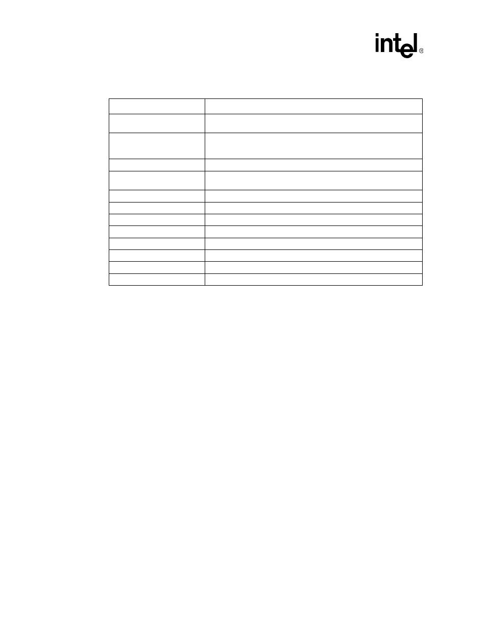
Table 2-1. Itanium
®
2 Processor System Bus Signal Groups
Group Name
Signals
AGTL+ Input Signals
BPRI#, BR[3:1]#, DEFER#, GSEQ#, ID[9:0]#, IDS#, RESET#
1
, RS[2:0]#,
RSP#, TRDY#
NOTES:
1. Signals will not be terminated on-die even when on-die termination (ODT) is enabled. See Intel
®
Itanium
®
2 Processor
Hardware Developer’s Manual for further details.
AGTL+ I/O Signals
A[49:3]#, ADS#, AP[1:0]#, BERR#, BINIT#, BNR#, BPM[5:0]#
, BR0#,
D[127:0]#, DBSY#, DEP[15:0]#, DRDY#, HIT#, HITM#, LOCK#, REQ[5:0]#,
RP#, SBSY#, STBN[7:0]#, STBP[7:0]#, TND#
AGTL+ Output Signals
FERR#, THRMTRIP#, DBSY[1:0]#, DRDY[1:0]#, SBSY[1:0]#
Special AGTL+ Asynchronous
Interrupt Input Signals
A20M#, IGNNE#, INIT#, LINT[1,0], PMI#
Power Good Signal
PWRGOOD
HSTL Clock Signals
BCLKn, BCLKp
TAP Input Signals
TCK, TDI, TMS, TRST#
TDO
System Management Signals
3.3V, SMA[2:0], SMSC, SMSD, SMWP, THRMALERT#
Power Signals
GND, VCTERM
LVTTL Power Pod Signals
CPUPRES#, OUTEN, PPODGD#
Other
TERMA, TERMB, TUNER1, TUNER2, VCCMON, VSSMON