Assembly instruction, Diagram 1 – Impex PHE 2000 User Manual
Page 7
ASSEMBLY INSTRUCTION
Tools Required Assembling the Machine: Two Adjustable Wrenches and Allen Wrenches
NOTE: It is strongly recommended this machine be assembled by two or more people
to avoid possible injury.
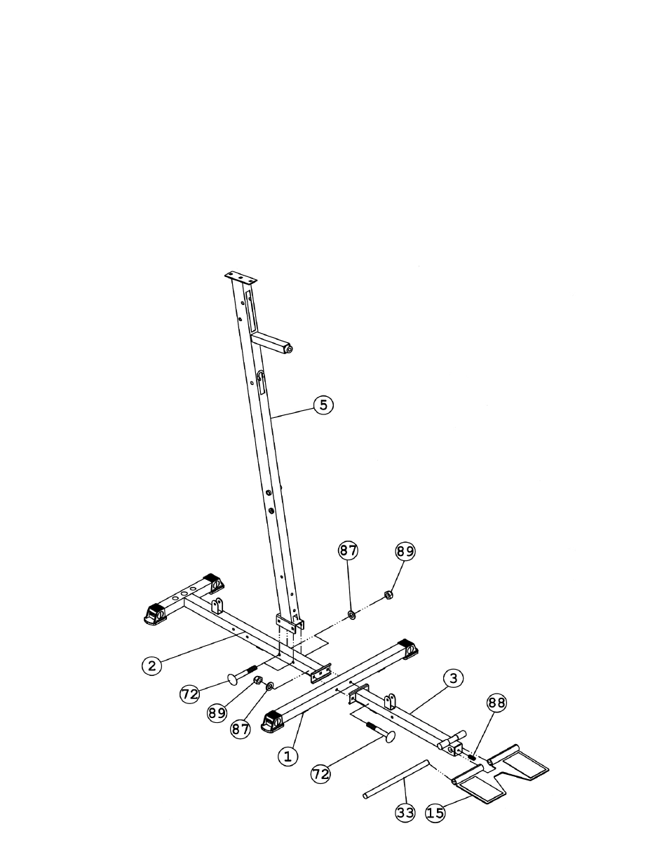
STEP 1 (See Diagram 1)
A.) Place the Middle Base Frame (#1) between the Front & Rear Base Frames (#2 & #3).
Align the holes. Secure them with two M10 x 2 ¾” Carriage Bolts (#72), two
∅
¾” Washers
(#87), and two M10 Aircraft Nuts (#89).
B.) Attach the Foot Plate (#15) to the Front Base Frame (#3). Align the holes. Insert the 15 ¾”
Foot Plate Axle (#33) through the holes. Secure the Axle with a M8 x ¾” Screw (#88).
C.) Attach the Vertical Frame (#5) to the Rear Base Frame (#2). Secure it with two M10 x 2 ¾”
Carriage Bolts (#72),
∅
¾” Washers (#87), and M10 Aircraft Nuts (#89). DO NOT tighten
the Nuts and Bolts yet.
DIAGRAM 1
6
- IGS-09 (11 pages)
- SAG-44.1 (10 pages)
- TSA-5682 (14 pages)
- MWM-1840 (29 pages)
- IGS-10 (10 pages)
- TC-6000 (12 pages)
- MWB-715N (12 pages)
- CR 5 (26 pages)
- MD-823 (15 pages)
- PL-43211 (14 pages)
- PL 10510 (12 pages)
- WM-1505 (22 pages)
- PHE1000 (20 pages)
- TSA-5762 (14 pages)
- IGS-5683 (13 pages)
- DBR 400 (7 pages)
- MWM7150 (21 pages)
- DBR 90 (11 pages)
- CG 1400 (24 pages)
- SB 208 (9 pages)
- IGS-02 (10 pages)
- MWB-356 (13 pages)
- AX-PWR7 (21 pages)
- MWB-855 (11 pages)
- TSA-410 (10 pages)
- TSA-41 (7 pages)
- WM 1403 (22 pages)
- DBR 92 (11 pages)
- MARCY TPL-40 (3 pages)
- MSS-1280 (27 pages)
- JD 2 (8 pages)
- PHC-700 (12 pages)
- Gold's Gym WMGG-224 (11 pages)
- MWM 800 (23 pages)
- WM-356 (13 pages)
- EVE-720 (13 pages)
- BF-1201 (22 pages)
- PT 360 (9 pages)
- CB-200 (11 pages)
- Olympic Cage (24 pages)
- EVE-900 (21 pages)
- PT-36 (7 pages)
- PHC-PWR9 (22 pages)
- MWM-1558 (20 pages)
- MWB-4360 (33 pages)