6 serial port connectors, 7 keyboard and mouse connector – Intel Server Board S5000PAL User Manual
Page 57
Connector / Header Locations and Pin-outs
Intel
®
Server Board S5000PAL / S5000XAL TPS
Revision
1.4
Intel order number: D31979-007
58
5.7.6
Serial Port Connectors
The server board provides one external RJ45 Serial ‘B’ port (J9A2) and one internal 9-pin Serial ‘A’ port
header (J1B1). The following tables define the pin-outs for each.
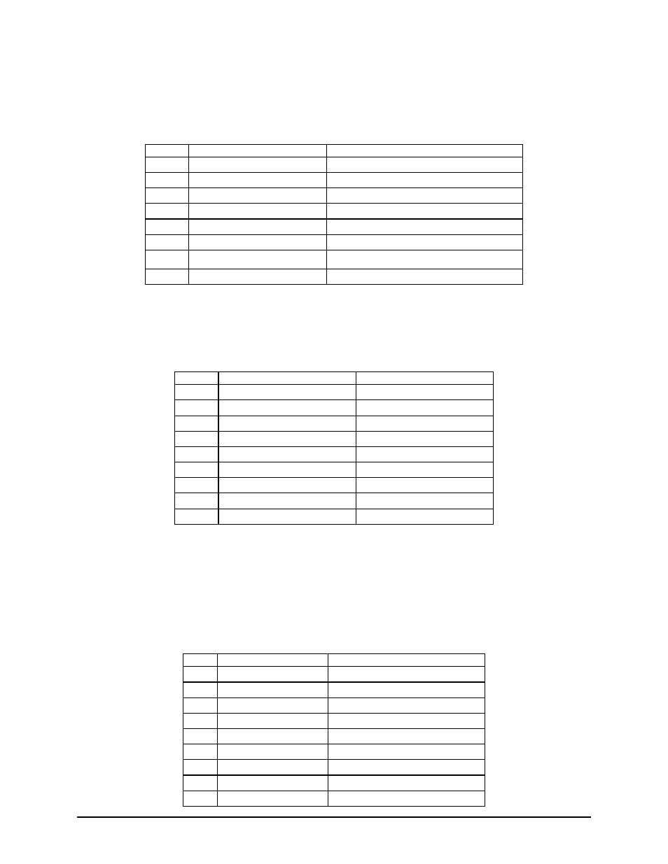
Table 27. External RJ-45 Serial ‘B’ Port Pin-out (J9A2)
Pin
Signal Name
Description
1
SPB_RTS
RTS (request to send)
2
SPB_DTR
DTR (Data terminal ready)
3
SPB_OUT_N
TXD (Transmit data)
4 GND
Ground
5
SPB_RI
RI (Ring Indicate)
6
SPB_SIN_N
RXD (receive data)
7 SPB_DSR
_DCD
Data Set Ready / Data Carrier Detect 1
8
SPB_CTS
CTS (clear to send)
Note:
1
A jumper block on the server board will determine whether DSR or DCD is routed to pin 7. The
board will have the jumper block configured with DSR enabled at production.
Table 28. Internal 9-pin Serial ‘A’ Header Pin-out (J1B1)
Pin
Signal Name
Description
1
SPA_DCD
DCD (carrier detect)
2
SPA_DSR
DSR (data set ready)
3
SPA_SIN_L
RXD (receive data)
4
SPA_RTS
RTS (request to send)
5
SPA_SOUT_N
TXD (Transmit data)
6
SPA_CTS
CTS (clear to send)
7
SPA_DTR
DTR (Data terminal ready)
8
SPA_RI
RI (Ring Indicate)
9 GND
Ground
5.7.7
Keyboard and Mouse Connector
Two stacked PS/2 ports (J9A1) are provided to support both a keyboard and a mouse. Either PS/2 port
can support a mouse or keyboard. The following table details the pin-out of the PS/2 connector.
Table 29. Stacked PS/2 Keyboard and Mouse Port Pin-out (J9A1)
Pin
Signal Name
Description
1 KB_DATA_F
Keyboard
Data
2
TP_PS2_2
Test point – keyboard
3 GND
Ground
4
P5V_KB_F
Keyboard / mouse power
5 KB_CLK_F
Keyboard
Clock
6
TP_PS2_6
Test point – keyboard / mouse
7 MS_DAT_F
Mouse
Data
8
TP_PS2_8
Test point – keyboard / mouse
9 GND
Ground