Intel Server Board S5000PAL User Manual
Page 40
Intel
®
Server Board S5000PAL / S5000XAL TPS
Functional Architecture
Revision 1.4
Intel order number: D31979-007
41
TP02303
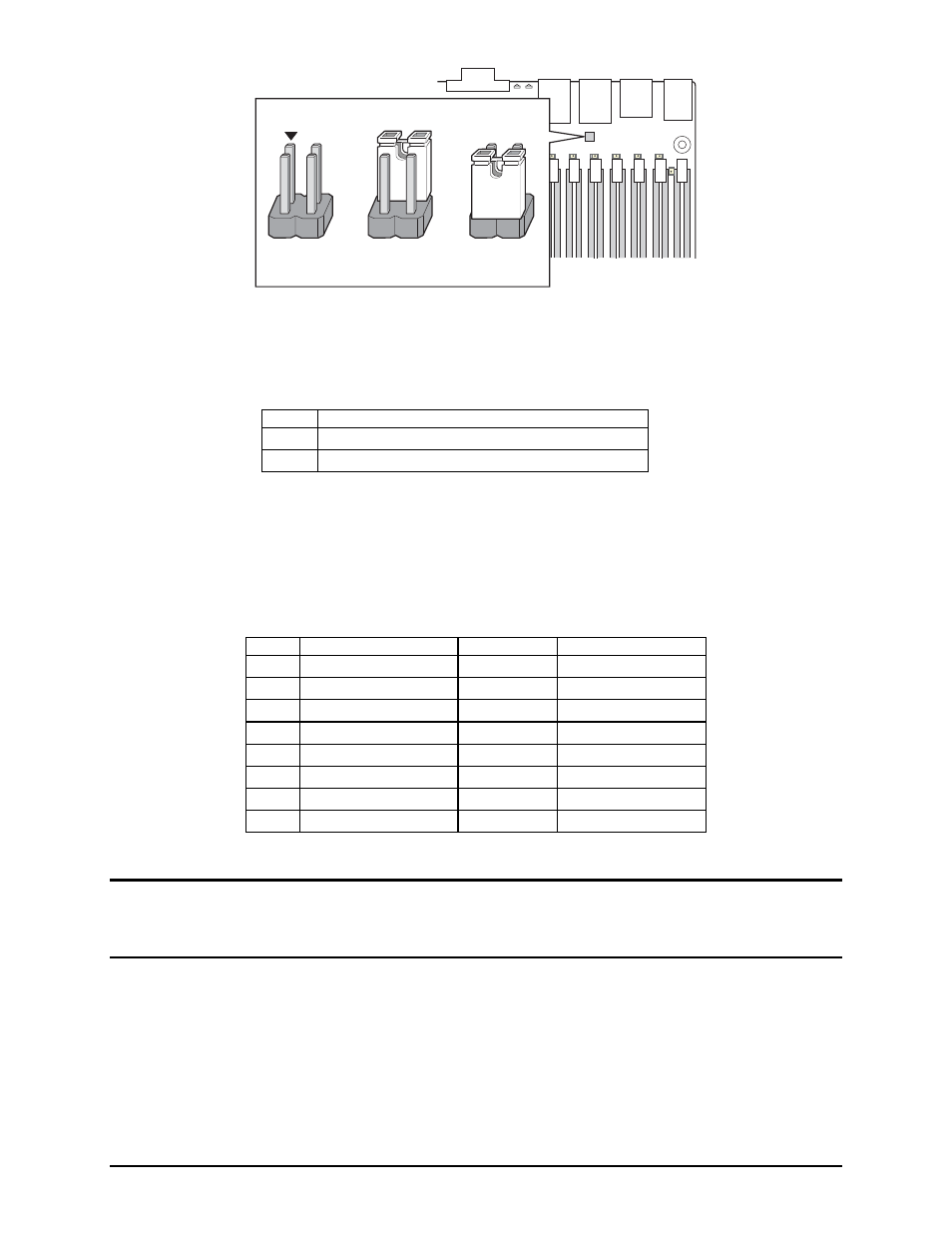
J8A3
1-2: DCD to DTR
3-4: DSR to DTR
(factory default)
2
4
3
Figure 15. Serial Port Configuration Jumper Location
For server applications that require a DB9 serial connector, an 8-pin RJ45-to-DB9 adapter must be used.
The following table provides the pin-out required for the adapter to provide RS232 support. A standard
DH10-to-DB9 cable and 8-pin RJ45 to DB9 DCD and DSR adapters are available from Intel in the Serial
Port Accessory Kit, product code: AXXRJ45DB92.
Table 9. Rear Serial B Port Adapter Pin-out
RJ45
Signal
Abbreviation
DB9
1
Request to Send
RTS
7
2
Data Terminal Ready
DTR
4
3 Transmitted
Data TD
3
4 Signal
Ground
SGND 5
5 Ring
Indicator
RI
9
6
Received Data
RD
2
7
DCD or DSR
DCD/DSR
1 or 6 (see note)
8
Clear To Send
CTS
8
Note:
The RJ45-to-DB9 adapter should match the configuration of the serial device used. One of two pin-
out configurations is used, depending on whether the serial device requires a DSR or DCD signal. The
final adapter configuration should also match the desired pin-out of the RJ45 connector, as it can also be
configured to support either DSR or DCD.
3.5.1.2
Floppy Disk Controller
The server board does not support a floppy disk controller (FDC) interface. However, the system BIOS
does recognize USB floppy devices.
3.5.1.3
Keyboard and Mouse Support
Dual stacked PS/2 ports, located on the back edge of the server board, are provided for keyboard and
mouse support. Either port can support a mouse or keyboard. Neither port supports hot plugging.
Pins
What happens at system reset…
1-2
Serial port is configured for DCD to DTR
3-4
Serial port is configured for DSR to DTR (default)