3 ide connector, 4 intel, I/o expansion module connector – Intel Server Board S5000PAL User Manual
Page 55
Connector / Header Locations and Pin-outs
Intel
®
Server Board S5000PAL / S5000XAL TPS
Revision
1.4
Intel order number: D31979-007
56
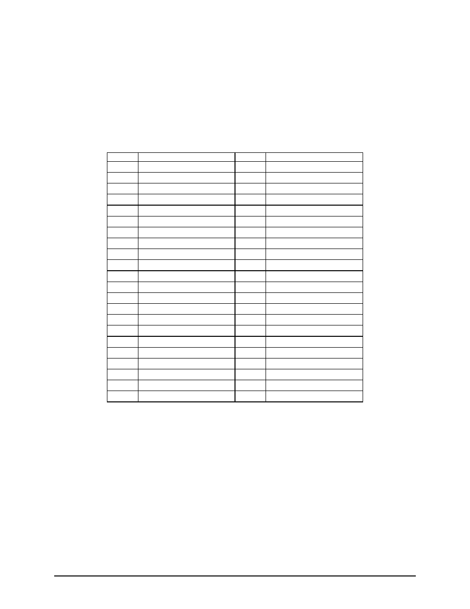
5.7.3 IDE
Connector
The server board includes an IDE connector to access the single IDE channel from the ESB-2 IO
controller hub. The design intent for this connector is to provide IDE support for a single slim-line optical
drive, such as CDROM or DVD. The connector is not a standard 40-pin IDE connector, instead it has 44
pins providing support for both power and IO signals. The pin-out for this connector is defined in the
following table.
Table 24. 44-pin IDE Connector Pin-out (J3G1)
Pin
Signal Name
Pin
Signal Name
1 ESB_PLT_RST_IDE_N 2 GND
3 RIDE_DD_7
4 RIDE_DD_8
5 RIDE_DD_6
6 RIDE_DD_9
7 RIDE_DD_5
8 RIDE_DD_10
9 RIDE_DD_4
10
RIDE_DD_11
11 RIDE_DD_3
12 RIDE_DD_12
13 RIDE_DD_2
14 RIDE_DD_13
15 RIDE_DD_1
16 RIDE_DD_14
17 RIDE_DD_0
18 RIDE_DD_15
19 GND
20 KEY
21 RIDE_DDREQ
22 GND
23 RIDE_DIOW_N
24 GND
25 RIDE_DIOR_N
26 GND
27 RIDE_PIORDY
28 GND
29 RIDE_DDACK_N
30 GND
31 IRQ_IDE
32 TP_PIDE_32
33 RIDE_DA1
34 IDE_PRI_CBLSNS
35 RIDE_DA0
36 RIDE_DA2
37 RIDE_DCS1_N
38 RIDE_DCS3_N
39 LED_IDE_N
40 GND
41 P5V
42 P5V
43 GND
44 GND
5.7.4 Intel
®
I/O Expansion Module Connector
The server board provides an internal 50-pin mezzanine style connector (J3B1) to accommodate
proprietary form factor Intel
®
I/O Expansion Modules, which expand the IO capabilities of the server board
without sacrificing an add-in slot from the riser cards. There are three planned IO modules for use on this
server board: external 4 port SAS, dual Gb NIC, and Infiniband*. For more detail on the supported IO
modules, please refer to the Intel
®
Server Board S5000PAL / S5000XAL IO Module Hardware
Specification
. The following table details the pin-out of the Intel
®
I/O Expansion Module connector.