2 power connectors – Intel Server Board S5000PAL User Manual
Page 44
Intel
®
Server Board S5000PAL / S5000XAL TPS
Connector / Header Locations and Pin-outs
Revision 1.4
Intel order number: D31979-007
45
Connector
Quantity
Reference Designators
Connector Type
Pin
Count
System Recovery
Setting Jumpers
4
J1D1, J1D2, J1D3, J3H1
Jumper
3
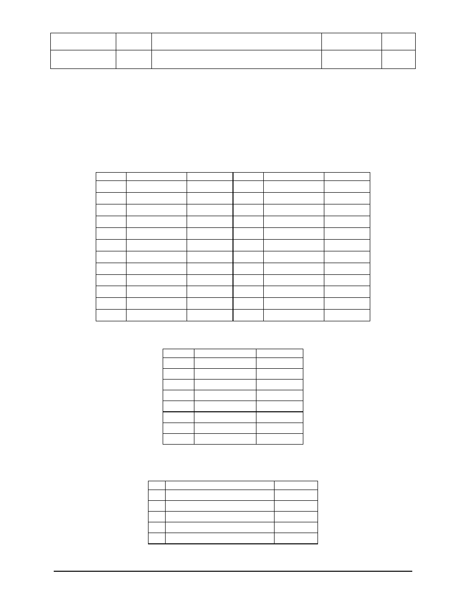
5.2 Power
Connectors
The main power supply connection is obtained using an SSI compliant 2x12 pin connector (J3K3). In
addition, there are two additional power related connectors; one SSI compliant 2x4 pin power connector
(J3K4) providing support for additional 12V, and one SSI compliant 1x5 pin connector (J1K1) providing
I
2
C monitoring of the power supply. The following tables define the connector pin-outs.
Table 11. Power Connector Pin-out (J3K3)
Pin
Signal
Color
Pin
Signal
Color
1
+3.3Vdc Orange
13
+3.3Vdc Orange
2 +3.3Vdc
Orange 14 -12Vdc
Blue
3
GND Black
15
GND Black
4 +5Vdc
Red 16 PS_ON# Green
5
GND Black
17
GND Black
6 +5Vdc
Red 18 GND
Black
7
GND Black
19
GND Black
8 PWR_OK Gray 20 RSVD_(-5V)
White
9 5VSB
Purple 21 +5Vdc
Red
10 +12Vdc
Yellow 22 +5Vdc
Red
11 +12Vdc
Yellow 23 +5Vdc
Red
12 +3.3Vdc
Orange 24 GND
Black
Table 12. 12V Power Connector Pin-out (J3K4)
Pin
Signal
Color
1 GND
Black
2 GND
Black
3 GND
Black
4 GND
Black
5 +12Vdc
Yellow/Black
6 +12Vdc
Yellow/Black
7 +12Vdc
Yellow/Black
8 +12Vdc
Yellow/Black
Table 13. Power Supply Signal Connector Pin-out (J1K1)
Pin
Signal
Color
1 SMB_CLK_ESB_FP_PWR_R Orange
2 SMB_DAT_ESB_FP_PWR_R Black
3 SMB_ALRT_3_ESB_R
Red
4 3.3V
SENSE-
Yellow
5 3.3V
SENSE+
Green