5 ssi control panel connector, 6 bridge board connector – Intel Server Board S5000PAL User Manual
Page 52
Intel
®
Server Board S5000PAL / S5000XAL TPS
Connector / Header Locations and Pin-outs
Revision 1.4
Intel order number: D31979-007
53
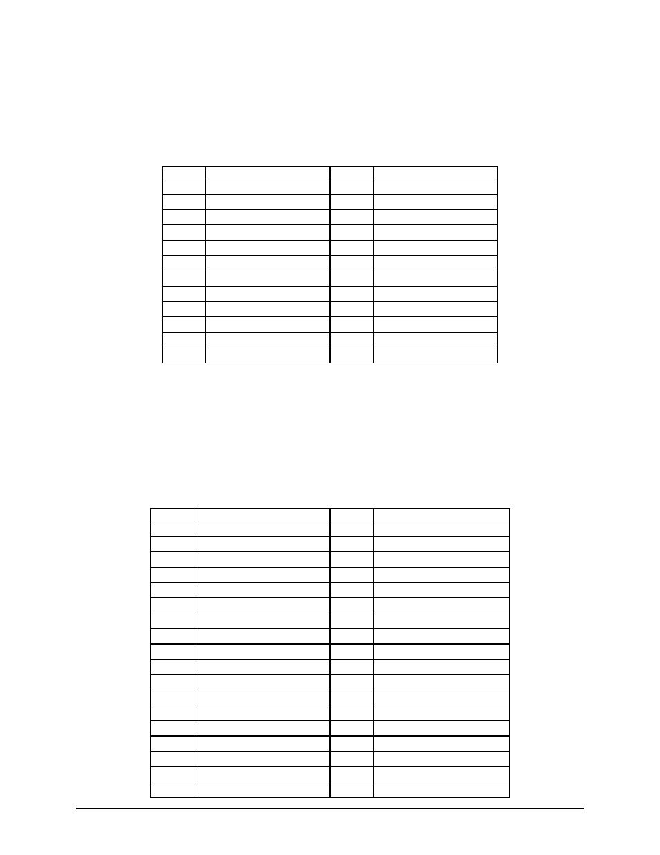
5.5 SSI Control Panel Connector
The server board provides a 24-pin SSI control panel connector (J3H2) for use with non-Intel chassis.
The following table provides the pin-out for this connector.
Table 20. Front Panel SSI Standard 24-pin Connector Pin-out (J3H2)
Pin
Signal Name
Pin
Signal Name
1 P3V3_STBY
2 P3V3_STBY
3 Key
4 P5V_STBY
5 FP_PWR_LED_L 6 FP_ID_LED_L
7 P3V3
8 FP_STATUS_LED1_R
9 HDD_LED_ACT_R 10
FP_STATUS_LED2_R
11 FP_PWR_BTN_L
12 LAN_ACT_A_L
13 GND
14 LAN_LINKA_L
15 Reset
Button
16 PS_I2C_3VSB_SDA
17 GND
18 PS_I2C_3VSB_SCL
19 FP_ID_BTN_L
20 FP_CHASSIS_INTRU
21 TEMP_SENSOR
22 LAN_ACT_B_L
23 FP_NMI_BTN_L
24 LAN_LINKB_L
5.6 Bridge Board Connector
For use in supported Intel
®
Server Chassis, the server board provides a 120-pin high-density bridge
board connector (J4G1) to route control panel, mid-plane, and backplane signals from the server board to
the specified system board. The following table provides the pin-outs for this connector.
Table 21. 120-pin Bridgeboard Connector Pin-out (J4G1)
Pin
Signal Name
Pin
Signal Name
A1 SMB_HOST_3V3_CLK B1 GND
A2 SMB_HOST_3V3_DAT B2 PE1_ESB_TXN_C<3>
A3 FM_BRIDGE_PRESENT_N
B3 PE1_ESB_TXP_C<3>
A4 GND
B4 GND
A5 PE1_ESB_RXN_C<3> B5 PE_WAKE_N
A6 PE1_ESB_RXP_C<3> B6 GND
A7 GND
B7 PE1_ESB_TXN_C<2>
A8 FM_FAN_D_PRSNT6 B8 PE1_ESB_TXP_C<2>
A9 GND
B9 GND
A10 PE1_ESB_RXN_C<2>
B10 FM_FAN_D_PRSNT5
A11 PE1_ESB_RXP_C<2>
B11 GND
A12 GND
B12 PE1_ESB_TXN_C<1>
A13
FM_FAN_D_PRSNT4
B13
PE1_ESB_TXP_C<1>
A14 GND
B14 GND
A15 PE1_ESB_RXN_C<1>
B15 RST_MP_PWRGD
A16 PE1_ESB_RXP_C<1>
B16 GND
A17 GND
B17 PE1_ESB_TXN_C<0>
A18 FM_RAID_PRESENT
B18 PE1_ESB_TXP_C<0>