English, 9 connectors introduction – Intel GA-N680SLI-DQ6 User Manual
Page 23
Hardware Installation
- 23 -
English
1-9
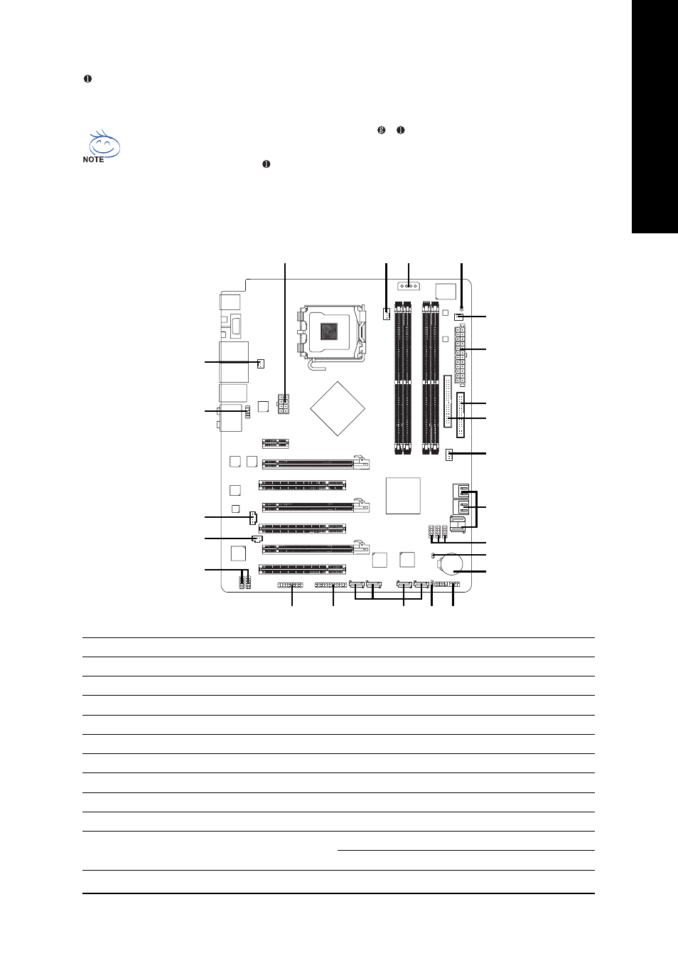
Connectors Introduction
2
1
4
22
8
10
9
15
19
16
5
12
MIC In
The default MIC In jack. Microphone must be connected to MIC In jack.
In addition to the default speakers settings, the ~
audio jacks can be reconfigured to
perform different functions via the audio software. Only microphones still MUST be connected
to the default Mic In jack (
). Please refer to the 2-/4-/6-/8- channel audio setup steps for
detailed software configuration information.
6
3
11
14
23
17
13
18
20
21
1)
ATX_12V_2X
2)
ATX (Power Connector)
3)
PCIE_12V
4)
CPU_FAN
5)
SYS_FAN
6)
PWR_FAN
7)
NB_FAN
8)
FDD
9)
IDE
10)
SATAII0 / 1 / 2 / 3 / 4 / 5
11)
GSATAII1-0 / GSATAII1-1 / GSATAII2-0 /
GSATAII2-1
12)
PWR_LED
13)
BATTERY
14)
F_PANEL
15)
F_AUDIO
16)
CD_IN
17)
SPDIF_IN
18)
F_USB1 / F_USB2 / F_USB3
19)
F1_1394 / F2_1394
20)
LPT
21)
TPM
22)
CI
23)
CLR_CMOS
7