1 enclosure chassis, Figure 1-2 enclosure chassis (front), Figure 1-3 enclosure chassis (rear) – IBM DCS9550 1S1 User Manual
Page 17: Enclosure chassis
Introduction
2
IBM System Storage DCS9550 1S1 Storage Expansion Unit Installation, Service, and User Guide
• Dummy drive carrier modules.
• Two AC, 450W Power Supply/Cooling plug-in modules (see
• One or two Serial ATA Control (SCM) Input/Output modules, dependent on configuration required: 1.5Gb
internal operating speed with 1 Gb or 2Gb external operating speed. (See
1.1.1
Enclosure Chassis
The chassis consists of a sheet metal enclosure assembly containing a Backplane PCB and module runner system
This chassis assembly also includes an integral Operators (Ops) Panel, mounted at the rear.
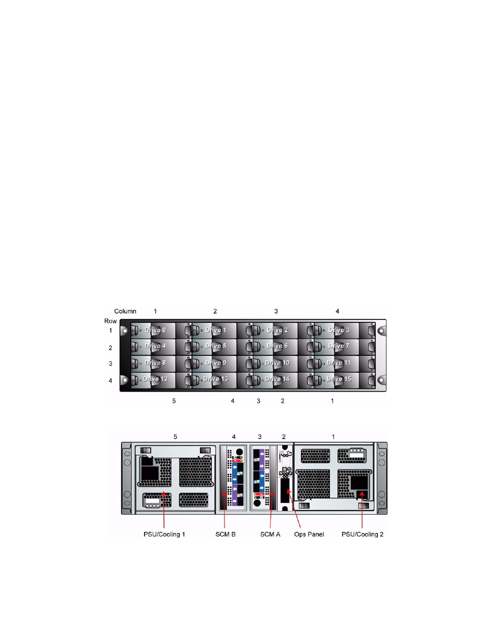
The chassis assembly contains 16 drive bays at the front, each of which accommodates a plug-in drive carrier
module. The 16 drive bays are arranged in 4 rows of 4 drives. At the rear, the chassis assembly contains the integral
ops panel and four module bays to house two Power Supply/Cooling modules, one SCM I/O module, and one blank
SCM module filler.
The Backplane PCB provides logic level signal and low voltage power distribution paths.
Figure 1–2
and
Figure 1–
3
show front and rear views of an RS-1602 chassis respectively.
Note
The DCS9550 1S1 Storage Expansion Unit is shipped in a preconfigured 42U rack configuration, except
for the top three in the rack with the controllers or top two in an expansion rack. Refer to the IBM System
Storage DCS9550 Installation, Service, and User Guide.
.
.
Figure 1–2
Enclosure Chassis (Front)
Figure 1–3
Enclosure Chassis (Rear)