Command structure, 3 command structure – Mocomtech CDM-570 User Manual
Page 10
CDM570/570L Satellite Modem
Incorporate NMCS Protocol
MN/CDM570L.AA4
Page 6 of 54
MN/CDM570L.AA4
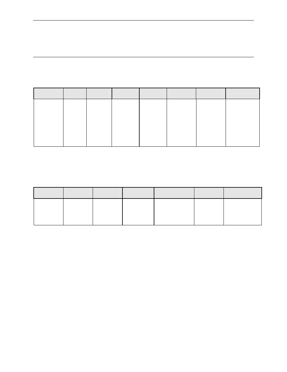
3.3 Command Structure
Controller-to-target:
Start of
Packet
Target
Address
Address
De-limiter
Instruction
Code
Row Index
(Optional)
Code
Qualifier
Optional
Arguments
End of Packet
<
ASCII
code 60
(1
character)
1 to 4
chars
/
ASCII
code 47
(1
character)
(3
characters)
1 to 3
characters
contained
within [ and
] brackets.
= or ?
ASCII code
61
or 63
(1
character)
(n
characters)
Carriage
Return
And
Line Feed.
ASCII code 13
and code 10
[ 0x0D 0x0A ]
(2 character)
Example:
<0135/TFQ=1949.2345{CR}
Example:
<1/rte[1]=
rt1|239.022.033.044.32|1|***************|0011|0|0|0|0|3
Target-to-controller:
Start of
Packet
Target
Address
Address
De-limiter
Instruction
Code
Code Qualifier
Optional
Arguments
End of Packet
>
ASCII
code 62
(1
character)
(4
characters)
/
ASCII
code 47
(1
character)
(3
characters)
=, ?, !, *, # or ~
ASCII code 61,
63, 33, 42, 35,
126
(1 character)
(From 0 to n
characters)
Carriage Return,
Line Feed
ASCII code
13,10
(2 characters)
Example: >0654/RSW=32{CR}{LF}
Example:
rt4|239.022.033.044.32|1|***************|0011|0|0|0|0|3