Cabling procedure for mvp-410st/810st – Multi-Tech Systems MULTIVOIP MVP-410ST/810ST User Manual
Page 100
Mechanical Installation & Cabling
MultiVOIP User Guide
100
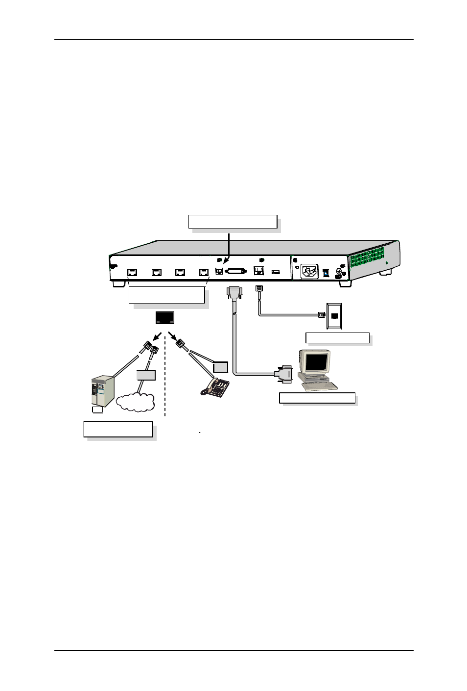
Cabling Procedure for MVP-410ST/810ST
Cabling involves connecting the MultiVOIP to your LAN and telephone
equipment.
1. Connect the power cord supplied with your MultiVOIP to a live AC
outlet and to the power connector on the back of the MultiVOIP as
shown at top right in Figure 3-14.
Ethernet Connection
Command Port Connection
COMMAND
ETHERNET
10 BASET
TERMINAL
MODE
ISDN-B RI Connections
ISDN1 & ISDN 2 : MVP410ST/810ST
ISDN3 & ISDN 4: MVP810ST only
IS DN 1
ISD N2
IS DN 3
ISD N4
?
NETWORK
MODE
ISDN
TA
PBX
PSTN
NT1
Device
*
* NT1 Device is needed
if PBX has “U” interface.
COMMAND
MODEM
Command Modem/TA connector
for remote configuration
Figure 3-14: Cabling for MVP-410ST/810ST
2. Connect the MultiVOIP to a PC by using a DB-25 (male) to DB-9
(female) cable. Plug the DB-25 end of the cable into the Command
port of the MultiVOIP and the other end into the PC serial port. See
Figure 3-14.
3. Connect a network cable to the ETHERNET 10BASET connector on
the back of the MultiVOIP. Connect the other end of the cable to your
network.