Setting the dc-in pcb and i/o pcb – Matsushita CF-74ECBAXBM User Manual
Page 37
9-15
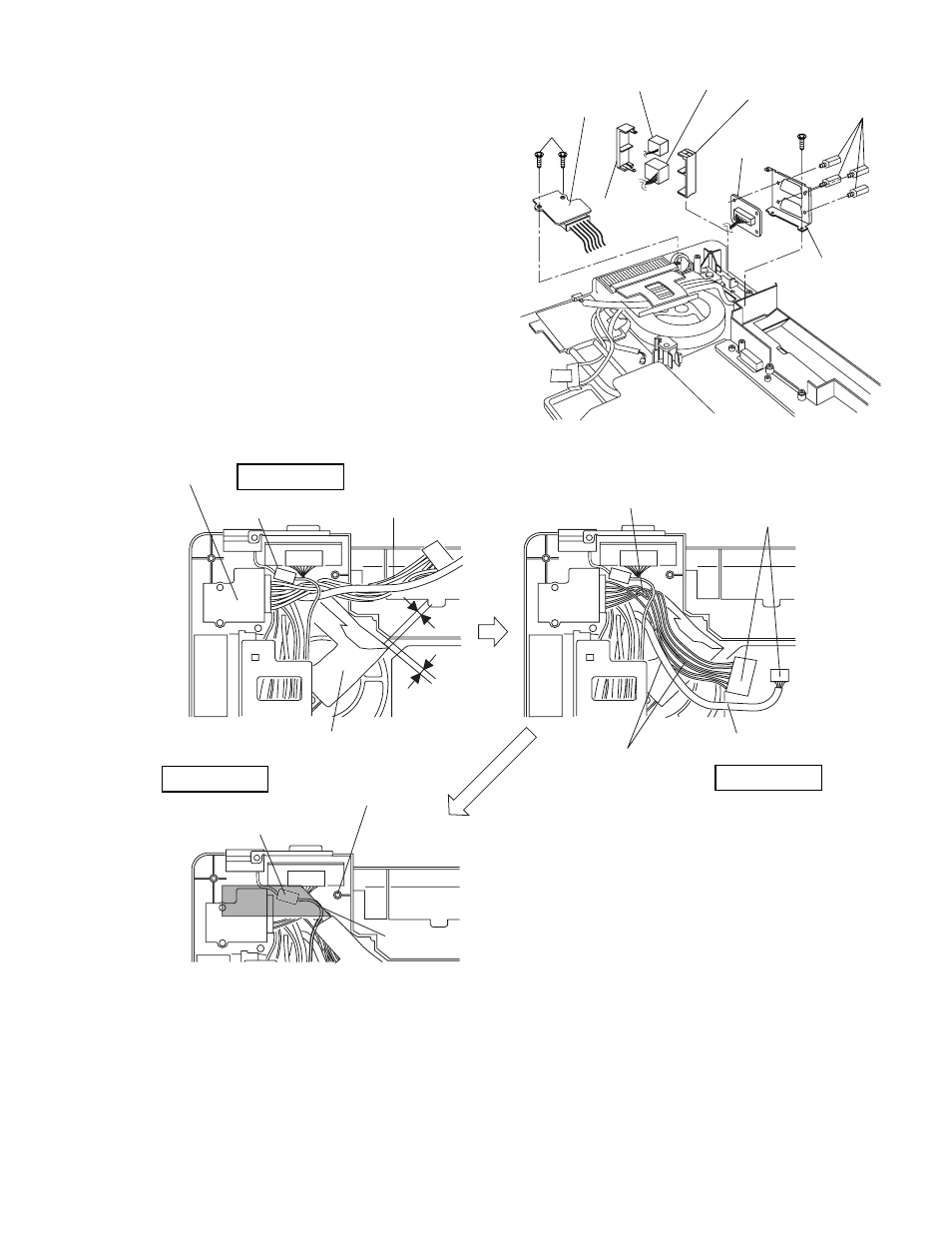
9.2.8.
Setting the DC-IN PCB and I/O PCB
1. Fit the Modem Cable and LAN Cable between the MOD-
ELAN Holders, and set them on to the computer.
2. Fix the I/O PCB to the I/O Plate using the four
Screws
3. Fix the I/O PCB with I/O Plate to the computer using the
two Screws
4. Fix the DC-IN PCB to the computer using the two
Screws
Screws
Screws
Q
Arranging the DC-IN Cable
DC-IN PCB
MODELAN-2
Holder
LAN Cable MODELAN
Holder
Modem Cable
I/O Plate
I/O PCB
DC-IN PCB
Set the Core of the Modem
over the DC-IN Cable.
DC-IN Cable
FAN Cable Sheet
0~3mm
0~3mm
Connect the Connector
Attach the Cable avoiding
overlapping
(DC-IN Cable and INV Cable).
Set the INV Cable under
the DC IN Cable.
Safety Working
Turn the DC-IN Cable halfway
(counterclockwise)
Safety Working
INV. Cable
Avoid runnning over the boss.
(Otherwise the Cable will be caught
at the Bottom Cabnet.)
Fix the Core using the Tape.
Safety Working
Fold back the end of Tape.