Removing the touch pad and pad pcb, Removing the finger pcb – Matsushita CF-74ECBAXBM User Manual
Page 28
9-6
1. Disconnect the LCD/INV. Cable from the Connector on
the Inverter.
2. Remove the LCD Unit.
3. Remove the Inverter with the Inverter Case.
4. Remove the two Screws
PCB L and R.
Screws
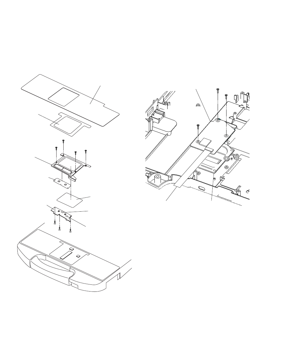
9.1.18. Removing the Touch PAD and PAD
PCB
1. Remove the Palm Rest Sheet.
2. Remove the four Screws
Ass'y.
3. Disconnect the two Cables from the two Connectors
(CN1301, CN1302).
4. Remove the three Screws
5. Remove the PAD Button WP Rubber and PAD SW PCB.
6. Remove the Touch PAD.
Screws
Screws
9.1.19. Removing the Finger PCB
Preparation
Perform the steps up to removing of the Main PCB.
1. Remove the three Screws.
2. Remove the Finger PCB and Finger Sensor Base.
Screws
Palm Rest Sheet
Pad WP Sheet A
PAD Base Ass’y
PAD Button
WP Rubber
Touch PAD
PAD SW PCB
CN1302
CN1301
Finger PCB
Finger Sensor Base
FP FFC Cable