Removing the pc card ejector and lithium battery, Removing the dc-in pcb and i/o pcb, Removing the fan motor and sd pcb – Matsushita CF-74ECBAXBM User Manual
Page 26
9-4
Note:
After replacing the Main Board, rewrite the BIOS ID.
1. Disconnect the ten Cables from the ten Connectors (CN6,
CN7, CN24, CN19, CN28, CN21, CN802, CN18, CN15,
CN25).
2. Remove the six Screws
3. Remove the Main PCB.
4. Remove the MP Guide.
Screws
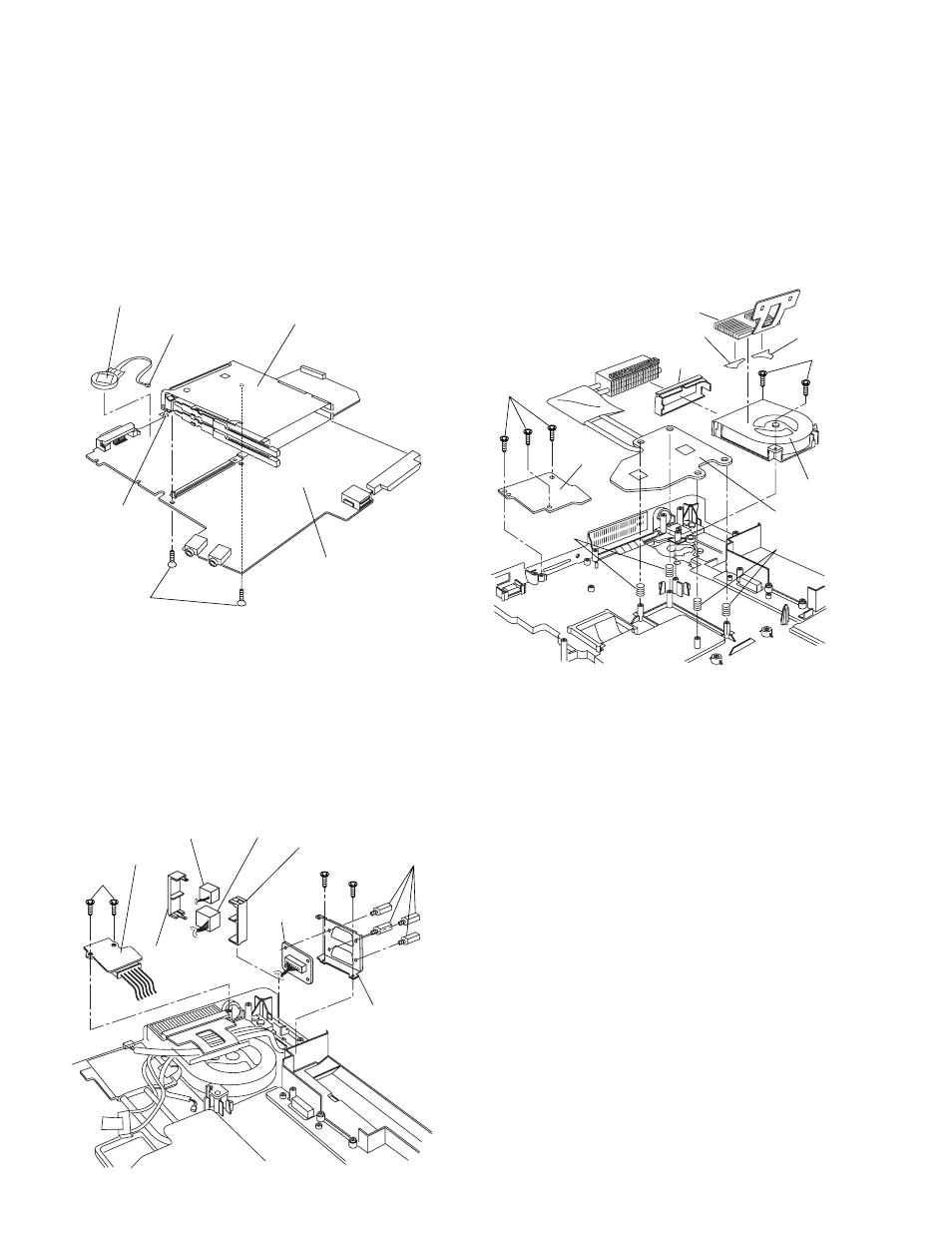
9.1.11. Removing the PC Card Ejector and
Lithium Battery
1. Remove the two Screws
2. Remove the PC Card Ejector.
3. Disconnect the Cable from the Connector (CN14).
4. Remove the Lithium Battery.
Screws
9.1.12. Removing the DC-IN PCB and I/O
PCB
1. Remove the two Screws
2. Remove the DC-IN PCB.
3. Remove the two Screws
4. Remove the four Screws
from the I/O Plate.
5. Remove the Modem Cable and LAN Cable from the
MODELAN Holders.
Screws
Screws
9.1.13. Removing the FAN Motor and SD
PCB
1. Remove the Cable Holder.
2. Remove the two Screws
3. Remove the FAN Motor.
4. Remove the Heat Sink, Fan Duct, and the four Heat Sink
Springs.
5. Remove the three Screws
6. Remove the SD PCB.
Screws
Screws
PC Card Ejector
Lithium Battery
(to CN14)
CN14
Main PCB
DC-IN PCB
MODELAN-2
Holder
LAN Cable MODELAN
Holder
Modem Cable
I/O Plate
I/O PCB
Cable Holder
FAN Motor
Heat Sink
Fan Duct
Fan Tape1
Fan Tape2
Heat Sink
Spring
Heat Sink
Spring
SD PCB