MTD -ERV 350 User Manual
Page 44
4
40 Instructions for the Installer
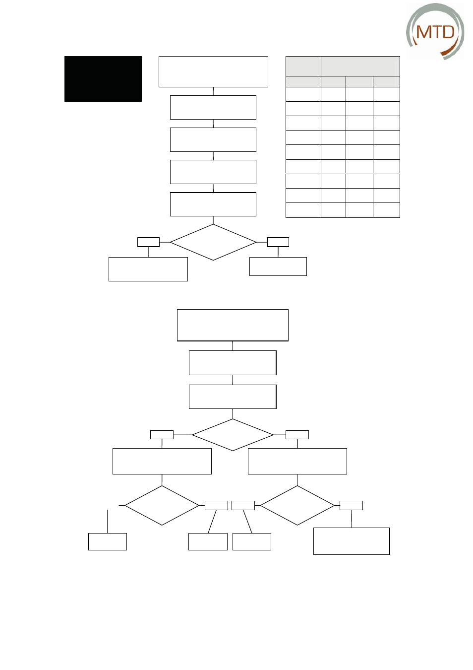
A1 / A2 / A3 / A4
Temperature sensor malfunction
T1 / T2 / T3 / T4
Remove the plug from
the socket
Remove the filter, the plastic
front cover and the metal cover
Remove temperature
sensor from the PCB
Check temperature sensor
resistance; see table
Is resistance OK?
Yes
No
Replace the PCB
CAUTION: Reset unit!
Replace the
temperature sensor
CAUTION!
Avoid contact with the
PCB and frost protection
element due to risk of
electrocution
A5 / A6
Motor bypass / frost protection element
malfunction
Remove the filter,
the plastic front cover and
the metal cover
Then initiate the
self-test (P76 on 1)
Is the motor
running?
Yes
No
Remove the motor and
the cog (incl. plastic part)
Is the cog defective?
No
Replace motor
Check connection and PCB;
12 VDC if motor is
running (see menu P76)
Does the
PCB register
current?
Yes
Replace motor
Yes
Replace cog
No
Replace the PCB
CAUTION: Reset unit!
Temp Resistance [K!]
oC
MIN
MED
MAX
10
19.570
19.904
20.242
15
15.485
15.712
15.941
18
13.502
13.681
13.861
19
12.906
13.071
13.237
20
12.339
12.491
12.644
21
11.801
11.941
12.082
22
11.291
11.420
11.550
25
9.900
10.000
10.100
30
7.959
8.057
8.155
[°C]
[K
Ω