3 wall mounting, 1 connection of the air ducts, 2 connection of the condensation drain – MTD -ERV 350 User Manual
Page 31
4
27
Instructions for the Installer
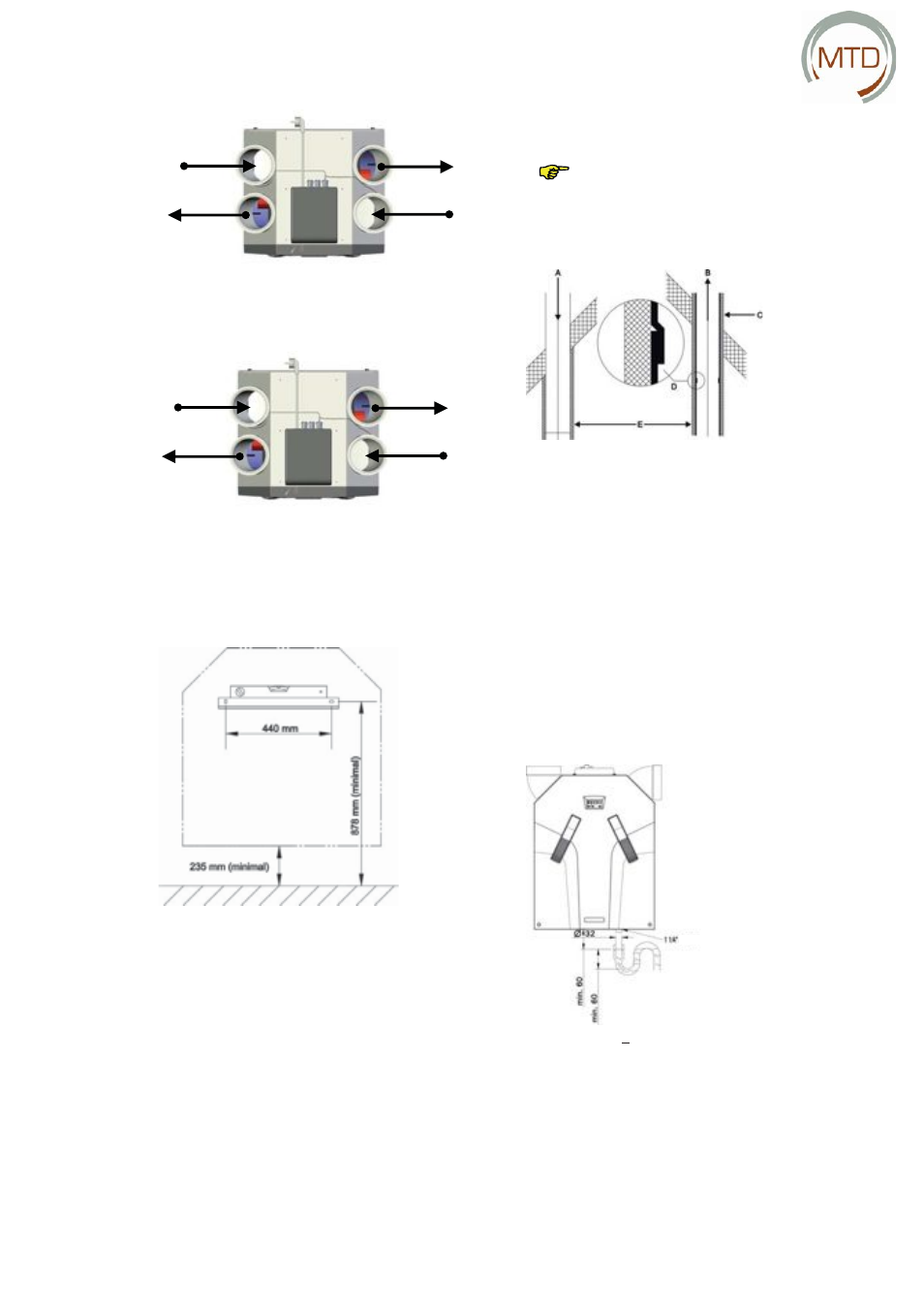
ComfoAir 350 – LEFT
Stale air
Outside air
Supply air
Exhaust air
ComfoAir 350 – RIGHT
Intake air
Exhaust air
Stale air
Outside air
4.3 Wall Mounting
LEFT
Connection
Install the MTD-ERV 350 on a wall with a load-bear-
ing capacity of at least 200 kg/m².
For other walls we recommend the use of a base for
installation on the fl oor (available as an option, see
section 4.8 with service parts). This helps to avoid
the transmission of structure-borne noise.
•
Fasten the supplied mounting bracket to the
wall horizontally.
•
Connect the condensation drain (not supplied)
to the underside of the MTD-ERV 350. The value
shown of 235 mm is only an indicative value.
The actual value depends on the type of con-
densation drain selected, see also section 4.3.2
for the connection of the condensation drain.
•
Ensure that at least 1 metre of space is left in
front of the MTD-ERV 350 for later maintenance
work.
No space is required to the sides of the MTD-ERV 350
for its proper operation.
Do not install the MTD-ERV 350 with a side
against a wall to avoid possible contact
noise.
4.3.1 Connection of the Air Ducts
Install a suitable silencer directly at the air intake and
air discharge connections. Information on silencers
is available from your supplier.
The air ducts to be connected, minimum diameter
150 mm, must be installed with as little air resistance
as possible and air tight.
•
Insulate the outside air duct and the stale air
duct vapour-tight between the roof/gable
opening and the MTD-ERV 350. This prevents
the formation of condensation on the outside
of the ducts.
•
Install the exhaust air duct with a gradient to-
wards the MTD-ERV 350.
4.3.2 Connection of the Condensation Drain
MTD-ERV 350