Chassis installation, Rear panel connectors, Keyboard and mouse connection – Global Upholstery Co. 2801330 User Manual
Page 74: Table 4-8, 7 chassis installation, 8 rear panel connectors
Page 87
KINO-LX Motherboard
The AT/ATX power connector is used to connect a chassis power On/Off button using an
adapter cable and is configured through the JP6 jumper. The AT/ATX power connector
has two operational modes:
1. Using
ATX power: AT/ATX power connects to an externally implemented power
switch, and the JP6 jumper should be left open.
2. Using
AT power: The pins on JP6 are shorted by a jumper cap. JP6 should be
shorted by default as the AMD Southbridge is designed without the consideration
for a power button signal. The shorted JP6 provides a hardware feedback to
initiate the system. The power on/off function is then managed by the AT power
switch button.
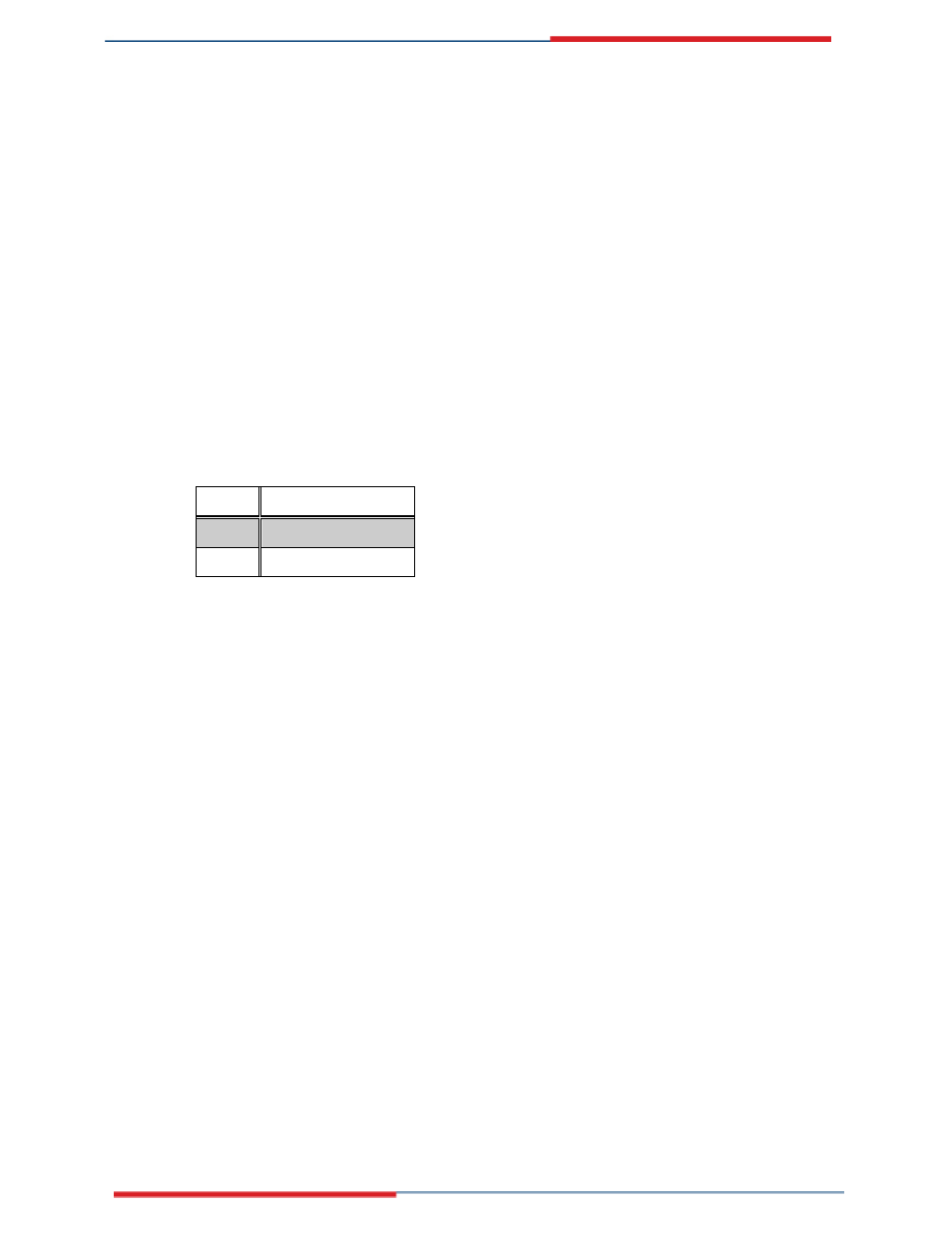
JP6 Description
Short
AT Mode (Default)
Open ATX
Mode
Table 4-8: AT/ATX Power Mode Select Jumper Settings
4.7 Chassis Installation
After the DIMM modules have been installed
and after the internal peripheral connectors
have been connected to the peripheral devic es and the jumpers have been configured,
To mount a board into a chassis, please refer to the chassis user guide that came with the
product.
4.8 Rear Panel Connectors
4.8.1 Keyboard and Mouse Connection
A PS/2 keyboard and a PS/2 mouse can be connected to the appropriate PS/2 connector
on the rear panel.