Lcd clock jumper, At/atx power mode select jumper, Table 4-6 – Global Upholstery Co. 2801330 User Manual
Page 73: 5 lcd clock jumper, 6 at/atx power mode select jumper
Page 86
IEI® Technology, Corp.
KINO-LX Motherboard
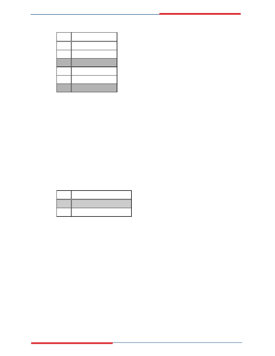
JP1 DESCRIPTION
1-3
COM1 RI Pin Use +12V
3-5
COM1 RI Pin Use +5V
7-9
COM1 RI Pin Use RI
2-4
COM2 RI Pin Use +12V
4-6
COM2 RI Pin Use +5V
8-10
COM2 RI Pin Use RI
Table 4-6: COM2 Voltage Setup Jumper Settings
4.6.5 LCD Clock Jumper
Jumper Label:
JP5
Jumper Type:
3-pin header
Jumper Settings:
See Table 4-7
Jumper Location:
The LCD clock jumper sets the LCD panel shift clock.
JP5 Description
1-2
Inverted Output (Default)
2-3 Normal
Output
Table 4-7: LCD Clock Jumper Settings
4.6.6 AT/ATX Power Mode Select Jumper
Jumper Label:
JP6
Jumper Type:
2-pin header
Jumper Settings:
See Table 4-8
Jumper Location:
The AT/ATX power mode select jumper block controls the connection to a power supply.