Basic controls – Grizzly COMBINATION SANDER G1183 User Manual
Page 5
model g1183/g1276 (mfg. since 3/10)
-3-
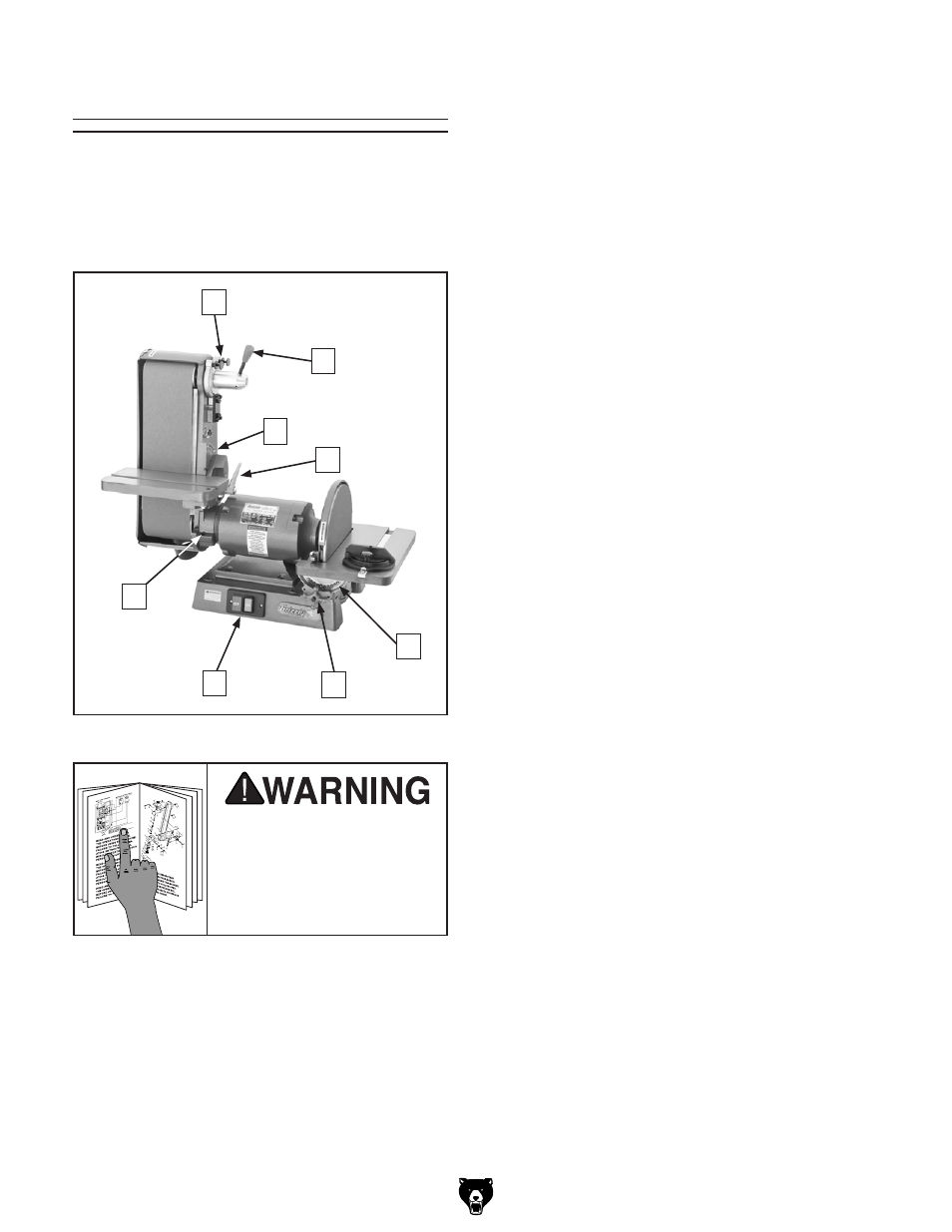
Basic Controls
having a good understanding of the basic con-
trols of the sander is important to properly set up
the machine and successfully complete the test
run. refer to
figure 5 and the following descrip-
tions to gain this understanding.
A. Upper Roller Adjustment Screws: Control
the tilt of the upper roller and are used to
make it parallel with the lower roller for track-
ing purposes.
B. Sanding Belt Quick-Release Tension
Lever: When pulled down, releases the ten-
sion on the sanding belt for removal/installa-
tion.
C. Sanding Belt Table Angle Scale: displays
the tilt angle of the belt table.
D. Sanding Belt Table Lock Lever: locks
the belt table in place after changing the tilt
angle.
E. Sanding Disc Table Angle Scale: displays
the tilt angle of the disc table.
f. Sanding Disc Table Lock Knob (1 of 2):
locks the disc table in place after changing
the tilt angle.
G. ON/Off Switch: turns the sander ON and
OFF.
H. Belt Assembly Locking Cap Screw:
secures the sanding belt assembly in place
after changing its tilt position.
figure 5. locations of the basic controls.
d
B
a
g
F
C
e
h
To reduce the risk of
serious injury when using
this machine, read and
understand this entire
manual before beginning
any operations.