Rigging, Nstallation, Igging – Goodman Mfg SS-CPC36-72 User Manual
Page 33
32
www.goodmanmfg.com
SS-CPC36-72
SS-CPC36-72
www.goodmanmfg.com
33
P
roduct
S
PecificationS
P
roduct
S
PecificationS
r
oof
C
UrB
i
nstallation
— r
igging
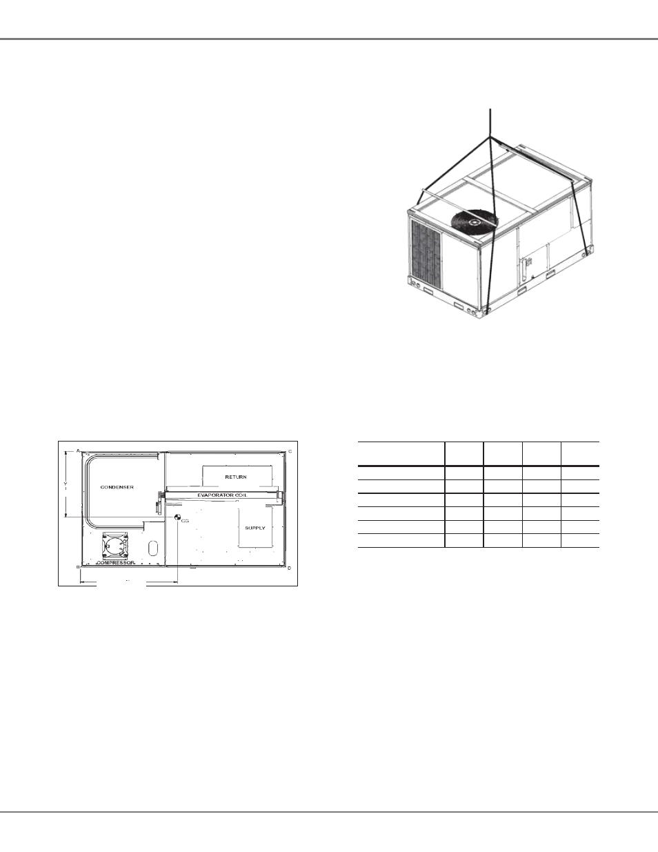
Provisions for forks have been included in the unit base frame. No other fork locations are
approved.
• Unit must be lifted by the four lifting holes located at the base frame corners.
• Lifting cables should be attached to the unit with shackles.
• The distance between the crane hook and the top of the unit must not be less than 60”.
• Two spreader bars must span over the unit to prevent damage to the cabinet by
the lift cables. Spreader bars must be of sufficient length so that cables do not
come in contact with the unit during transport. Remove wood struts mounted be-
neath unit base frame before setting unit on roof curb. These struts are intend-
ed to protect unit base frame from fork lift damage. To remove the struts, ex-
tract the sheet metal retainers and pull the struts through the base of the unit.
Refer to rigging label on the unit.
Important: If using bottom discharge with roof curb, duct-work should be attached to the
curb prior to installing the unit. Duct-work dimensions are shown in Roof Curb Installation
Instructions Manual.
Refer to the Roof Curb Installation Instructions for proper curb installation. Curbing must be
installed in compliance with the National Roofing Contractors Association Manual.
Lower unit carefully onto roof mounting curb. While rigging the unit, the center of gravity will
cause the condenser end to be lower than the supply air end.
Bring condenser end of unit into alignment with the curb. With condenser end of the unit resting on curb member and using curb as a fulcrum,
lower opposite end of the unit until entire unit is seated on the curb. When a rectangular cantilever curb is used, take care to center the unit. Check
for proper alignment and orientation of supply and return openings with duct.
To assist in determining rigging requirements, unit weights are shown below.
C
orner
& C
enter
-
of
-g
ravity
l
oCations
30”
Compressor
Return
Evaporator Coil
Supply
Condenser
Coil
37”
Unit Weights
3-Ton
Weights
4-Ton
Weights
5-Ton
Weights
6-Ton
Weights
Corner Weight (A)
115
120
130
150
Corner Weight (B)
150
150
160
190
Corner Weight (C)
105
105
115
130
Corner Weight (D)
130
135
150
170
Unit Shipping Weight
525
540
580
665
Unit Operating Weight
500
515
555
640
Note: Weights are calculated without accessories installed.
Curb installations must comply with local codes and should follow the established guidelines of the National Roofing Contractors Association.
Proper unit installation requires that the roof curb be firmly and permanently attached to the roof structure. Check for adequate fastening method
prior to setting the unit on the curb.
Full perimeter roof curbs are available from the factory and are shipped unassembled. The installing contractor is responsible for field assembly,
squaring, leveling, and mounting on the roof structure. All required hardware necessary for the assembly of the sheet metal curb is included in
the curb accessory package.
• Determine sufficient structural support before locating and mounting the curb and package unit.
• Duct-work must be constructed using industry guidelines. The duct-work must be placed into the roof curb before mounting the package unit.
Our full perimeter curbs include duct connection frames to be assembled with the curb. Cantilevered-type curbs are not available from the
factory.
• Contractor furnishes curb insulation, cant strips, flashing, and general roofing material.
• Support curbs on parallel sides with roof members. To prevent damage to the unit, the roof members cannot penetrate supply and return duct
openings.
Note: The unit and curb accessories are designed to allow Down Shot duct installation before unit placement. Duct installation after unit placement
is not recommended. See the manual shipped with the roof curb for assembly and installation instructions.