Installing the second unit, Step d1, Step d2 – GTO RB923 rev User Manual
Page 41
38
Step D1:
Attach the closed position
stop plate vertically to the
inside bottom of the gate
that will receive the
second operator (for push-
to-open, install plate on
outside of gate). In this
illustration this is the gate
that will close first.
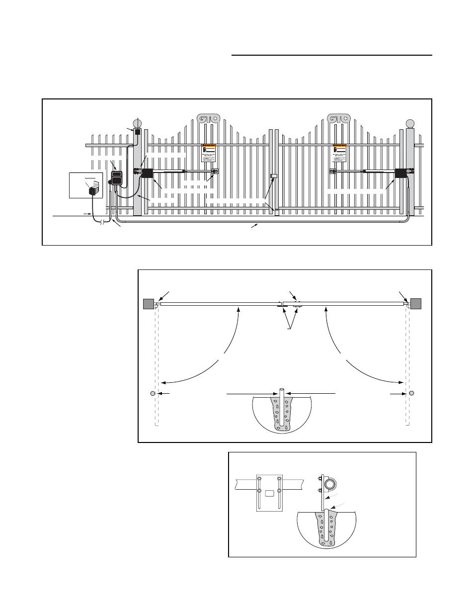
Installing The Second Unit
Step D2:
Install a closed position ground stop in driveway securely
into ground directly below the gate. The positive stop
plate installed in Step D1 should rest against the ground
stop in the closed position. For added security, install a
GTO Automatic Gate Lock (see Accessory Catalog).
The diagram below shows a dual gate, pull-to-open (gate opens into the property) installation on iron gates.
If you are installing a Push-to-Open (gate opens out) system see Push-to-Open Installation starting on page 31.
The open position stop for
the second gate is installed
the same as the first gate.
See instructions on page 16.
The Closed position stops
on a dual gate system
require a ground stop for
the second gate (first to
close) to be installed as
follows:
Receiver
Run up to 1000' of low
voltage wire to control
box from transformer.
(wire not included)
120 Volt Indoor
Transformer
(Surge Protector,
not supplied)
PVC conduit (not included) to protect wire from lawnmowers and weedeaters.
Control Box with Battery
Power Cable
Closed Position Positive Stop Plate
Gate Bracket
Post Bracket Assembly
GTO/PRO 2000 – First Operator
GTO/PRO 2200 – Second Operator
Closed Position
Stop Plates
Closed Position Stop Plate mounted
on second gate (first gate to close).
Open Position Stop
Wood, metal, or concrete
post set in concrete.
Gate Hinge
Gate Hinge
Open Position Stop
Not to exceed 110°
Not to exceed 110°
Closed position stop plate
Low profile ground stop
in middle of driveway
FRONT VIEW
SIDE VIEW
Ground Stop (under gate)