Service – Graco Inc. UNICARB Pro AA4500 User Manual
Page 38
38 308936
Service
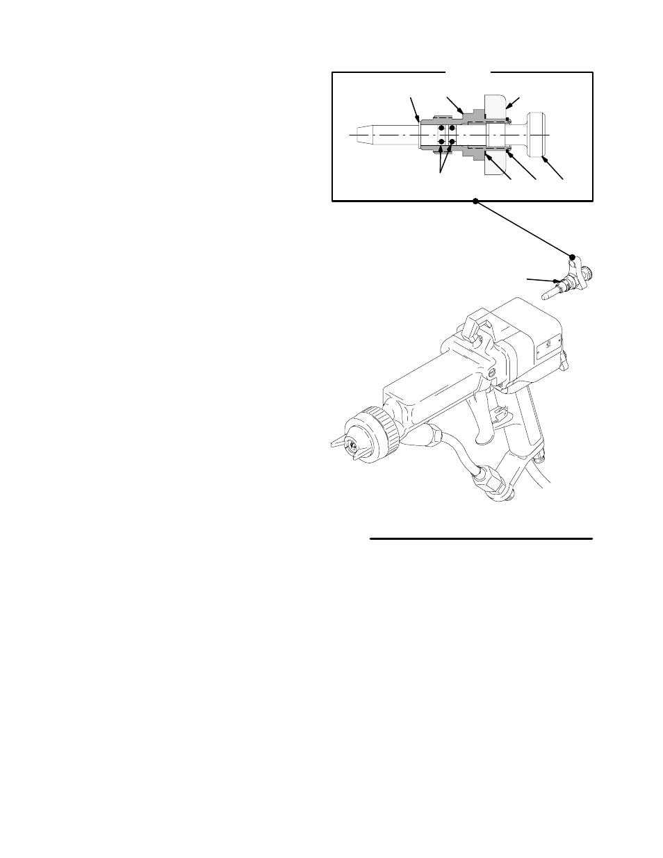
Air Control Valve Repair
NOTE: The air control valve (43) can be replaced as
an assembly or as individual parts.
To disassemble the air control valve,
1.
Prepare the gun for service as instructed on page
28.
2.
Remove the retaining ring (43h). See Fig. 19.
3.
Slide the KV HI-LO lever (43g) up, place a wrench
on the flats of the valve housing and remove the
air control valve assembly (43).
4.
Remove the retaining ring (43b).
5.
Rotate the adjustment knob (43c) counterclock-
wise until it is disengaged from the valve housing
threads (43d). Pull the adjustment knob out of the
valve housing. The KV HI-LO lever (43g) and the
wave spring (43f) can be removed if necessary.
6.
Clean all the parts and inspect them for wear or
damage.
7.
Reassemble the air control valve (43). Lubricate
the o-rings (43e) and the adjustment knob threads
(43c) with petroleum jelly. Install the retaining ring
(43h).
8.
Apply low strength (purple) Loctite or equivalent
thread sealant to the threads of the valve housing
(43d) and install the air control valve assembly
(43) into the gun handle.
To start the valve housing (43d) threads into the
handle, turn the adjustment knob (43c). Once the
threads are started, turn the adjustment knob (43c)
fully counterclockwise.
Torque the valve housing into the gun handle to 10
to 12 in-lb (1.1 to 1.4 N
Sm).
9.
Install the retaining ring (43h) back into the groove
in the valve housing (43d).
0385A
01954B
Fig. 19
DETAIL
43
43b
43d
43c
43h
43e
43g
43f
Lubricate o-rings (43e) and top knob
threads (43c) with petroleum jelly
Apply low strength (purple) Loctite or
equivalent to housing (43d) threads;
Torque to 10–12 in-lb (1.1–1.4 N.m)