Service, Caution – Graco Inc. UNICARB Pro AA4500 User Manual
Page 36
36 308936
Service
Turbine Alternator Removal and
Replacement
NOTE: Replace turbine bearings after 2000 hours of
operation. See your authorized Graco representative.
1.
Prepare the gun for service as instructed on page
28.
2.
Remove the power supply from the gun handle as
instructed on page 35.
3.
Squeeze the two ends of the retaining ring (35)
together and carefully pull the alternator (37) away
from the power supply (18) until the 3-wire connec-
tor (F) disengages. See Fig. 16.
4.
Use an ohmmeter to test the turbine alternator coil.
Measure the resistance between the two outer
terminals of the 3-wire connector (F). Resistance
should be 3 to 5 ohms. If the reading varies from
this value, replace the alternator.
5.
Measure the resistance between each outer
terminal of the 3-wire connector and the turbine
alternator housing. The resistance should be
infinite. If the resistance is not infinite, replace the
alternator.
6.
Connect the 3-wire connector to the 3 prongs in
the power supply. Push the alternator (37) onto the
power supply (18) until the retaining ring (35)
engages with the alternator.
7.
Install the power supply in the gun handle as
instructed on page 35.
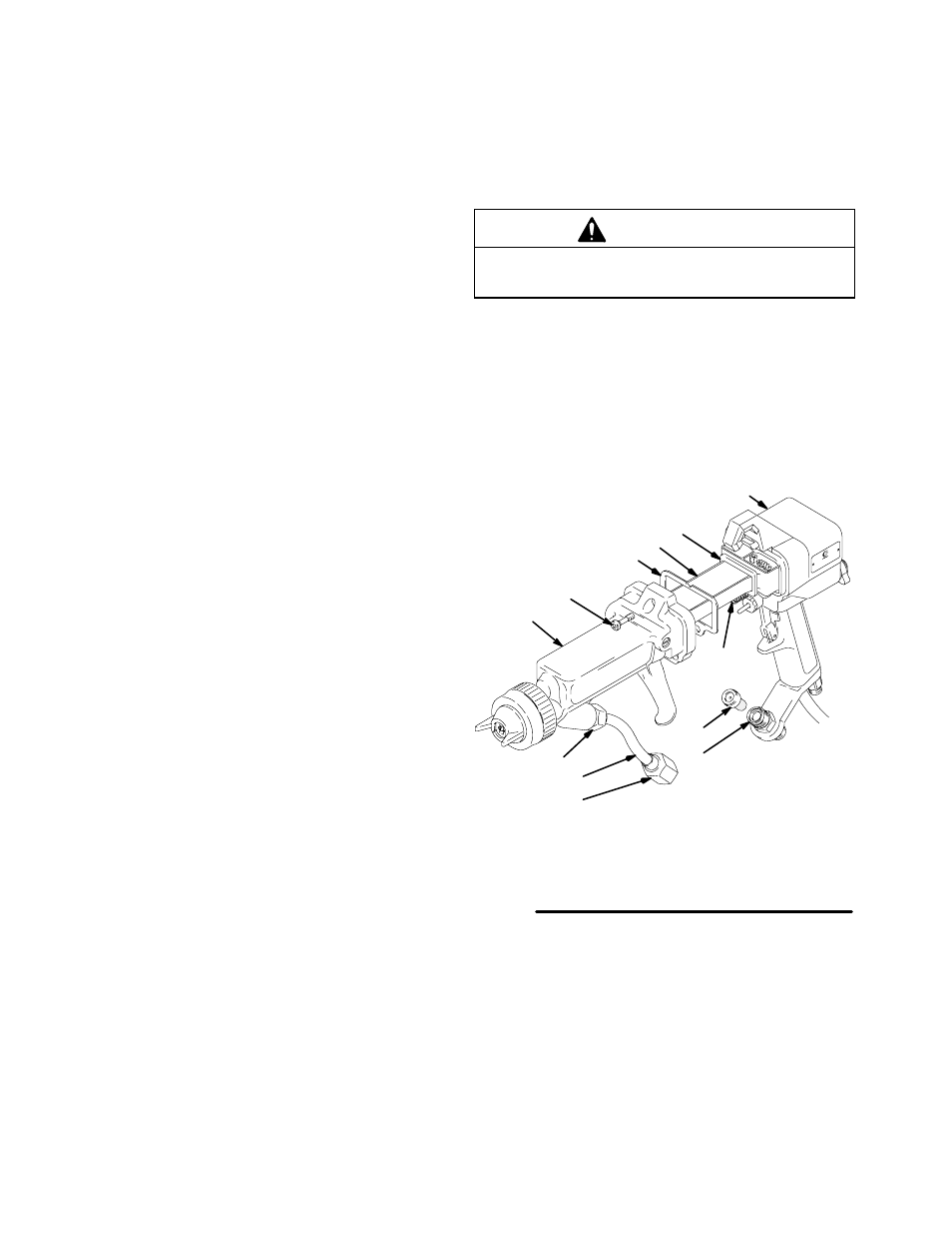
Barrel Installation
1.
Be sure the gaskets (34 & 18a) and spring (30) are
in place. See Fig. 17. Replace if damaged.
2.
Place the barrel (3) over the power supply (18) and
onto the gun handle (7). Make sure the fluid nee-
dle spring (30) is seated properly.
3.
Pressing the barrel and handle together, tighten
the three cap screws (5) oppositely and evenly
with the 4 mm driver (55). Tighten the cap screws
to 18 in-lbs (2 N
Sm) maximum (about a half turn
past snug). Do not over-tighten.
CAUTION
To avoid damaging the gun, do not over-tighten the
cap screws (5).
4.
Make sure the fluid filter (14) is in place in the fluid
fitting (10).
5.
Tighten the bottom fluid tube nut (C) onto the fluid
fitting (10); make sure the top fluid tube nut (D)
remains tightened.
6.
Test the gun resistance as instructed on page 25.
01952A
Fig. 17
3
34
30
18
5
7
12
18a
10
C
14
D
Tighten to 18 in-lbs (2 N
Sm) maximum (about half turn past
snug), using wrench provided.