Nno ot tiic ce e – Grizzly G4000 User Manual
Page 24
G4000 9'' x 19'' Lathe
-23-
N
NO
OT
TIIC
CE
E
S
Slliip
p C
Cllu
uttc
ch
h::
To avoid overloading the drive, a
safety slip clutch is fitted in the idler pulley.
Overloading the drive at slower speeds (rattling
noise) means the depth of cut is too deep and
should be reduced.
E
Ex
xa
am
mp
plle
e o
off G
Ge
ea
arr S
Se
ett--U
Up
p tto
o C
Cu
utt 1
10
0 T
T..P
P..ll..::
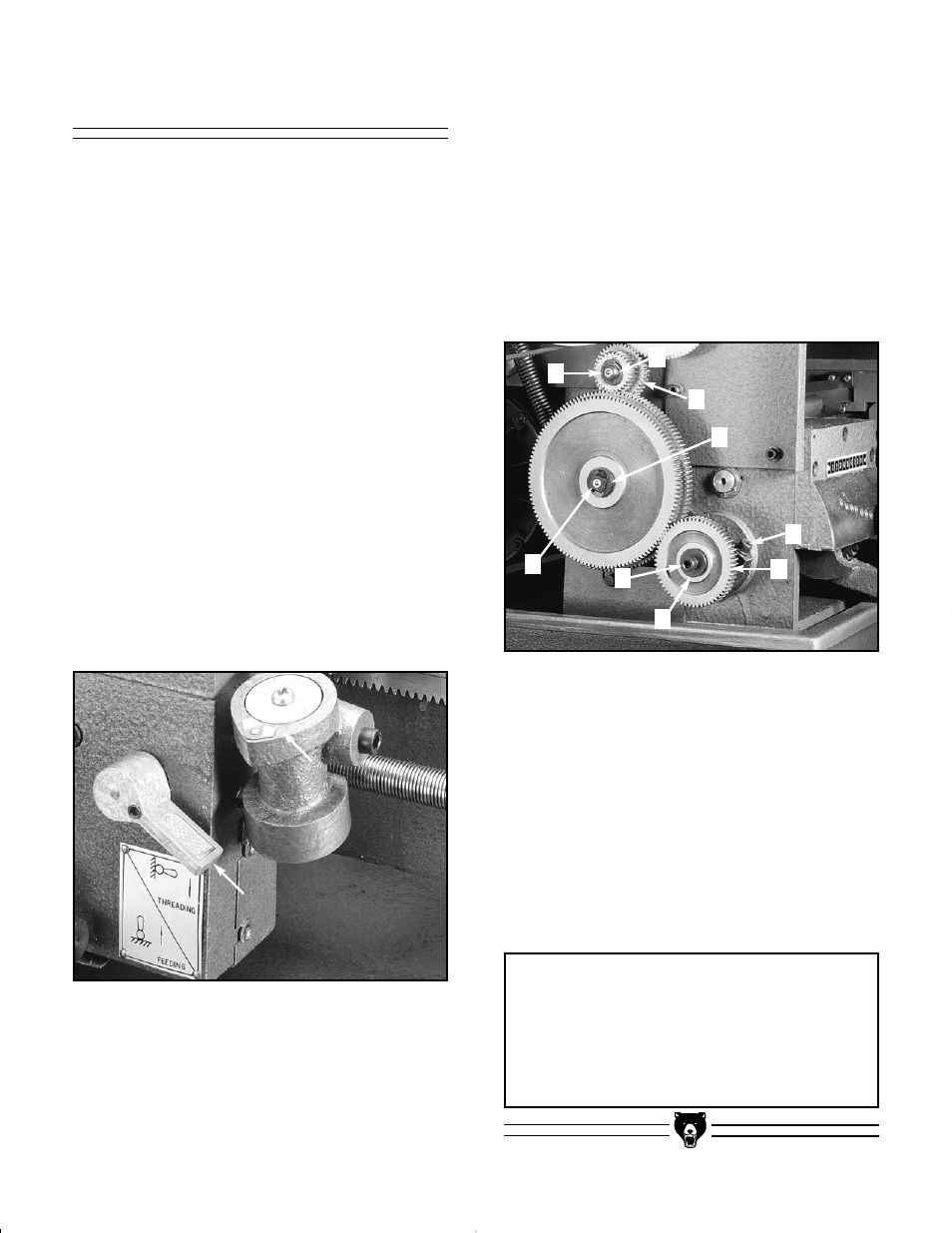
1
1..
Loosen cap screw
((1
1))
.
F
Fiig
gu
urre
e 3
35
5..
2
2..
Loosen bolt
((2
2))
. Remove washers
((3
3))
and
gear
((6
6))..
3
3..
Loosen bolts
((7
7))
to allow movement in the
center gear position.
4
4..
Loosen nuts
((5
5))..
Remove washer
((4
4))
and
gear
((8
8))..
R
Re
ea
as
ss
se
em
mb
blle
e a
as
s ffo
ollllo
ow
ws
s::
1
1..
Install 30 tooth gear in position
((6
6))
with bush-
ings, washer, and bolt.
2
2..
Install 60 tooth gear in position
((8
8))..
3
3..
Center 127 tooth gear remains in place.
4
4..
Adjust gear to mesh with upper and lower
gear and tighten bolts
((7
7))..
T
Th
hrre
ea
ad
d C
Cu
uttttiin
ng
g
Several different threads can be cut using the
proper combination of gears and settings. When
cutting inch threads, the half nut and threading
dial are used to thread in a conventional manner.
F
Fiig
gu
urre
e 3
34
4..
The thread dial chart specifies at
which point a thread can be entered using the
threading dial.
M
Me
ettrriic
c T
Th
hrre
ea
ad
d C
Cu
uttttiin
ng
g
- The only difference in
metric thread cutting is,
tth
he
e h
ha
allff n
nu
utt m
mu
us
stt
rre
em
ma
aiin
n e
en
ng
ga
ag
ge
ed
d d
du
urriin
ng
g tth
he
e e
en
nttiirre
e tth
hrre
ea
ad
diin
ng
g
p
prro
oc
ce
es
ss
s..
The thread dial cannot be utilized.
Set the machine up for the desired thread pitch.
Start the machine and engage the half nut. When
the tool reaches the workpiece, it will cut the ini-
tial threading pass. When the tool reaches the
end of the cut, stop the machine by turning the
motor off and at the same time back the tool out
of the workpiece so that it clears the thread.
D
Do
o
n
no
ott
disengage the half nut lever. Reverse the
motor direction to allow the cutting tool to traverse
back to the starting point. Repeat these steps
until you have obtained the desired results.
F
Fiig
gu
urre
e 3
34
4..
Half nut and threading dial.
F
Fiig
gu
urre
e 3
35
5..
Gear train adjustment points.
5
5
4
4
8
8
4
4
7
7
2
2
3
3
6
6
1
1