Jointer v-belt – Grizzly G0604 User Manual
Page 16
-14-
G0604 6" X 56" Jointer
Components and Hardware Needed:
Qty
Jointer Assembly ............................................... 1
Stand Assembly w/Motor ................................... 1
Cap Screws M8-1.25 x 25 ................................. 4
Lock Washers 8mm ........................................... 4
To mount the jointer to the stand:
1. Remove the rear cover from the jointer
stand.
2. With the help of an assistant, lift the jointer
onto the stand.
3. Align the mounting holes on the jointer and
stand.
4. Secure the jointer to the stand with the cap
screws and washers as shown in
Figure 6.
The jointer is heavy. Seek
assistance when lifting it
onto the jointer stand.
Components and Hardware Needed:
Qty
V-Belt ................................................................. 1
Belt Guard ......................................................... 1
Flange Bolts M6-1 x 12 ..................................... 2
Hex Nuts 6mm ................................................... 2
Flat Washers 6mm ............................................ 2
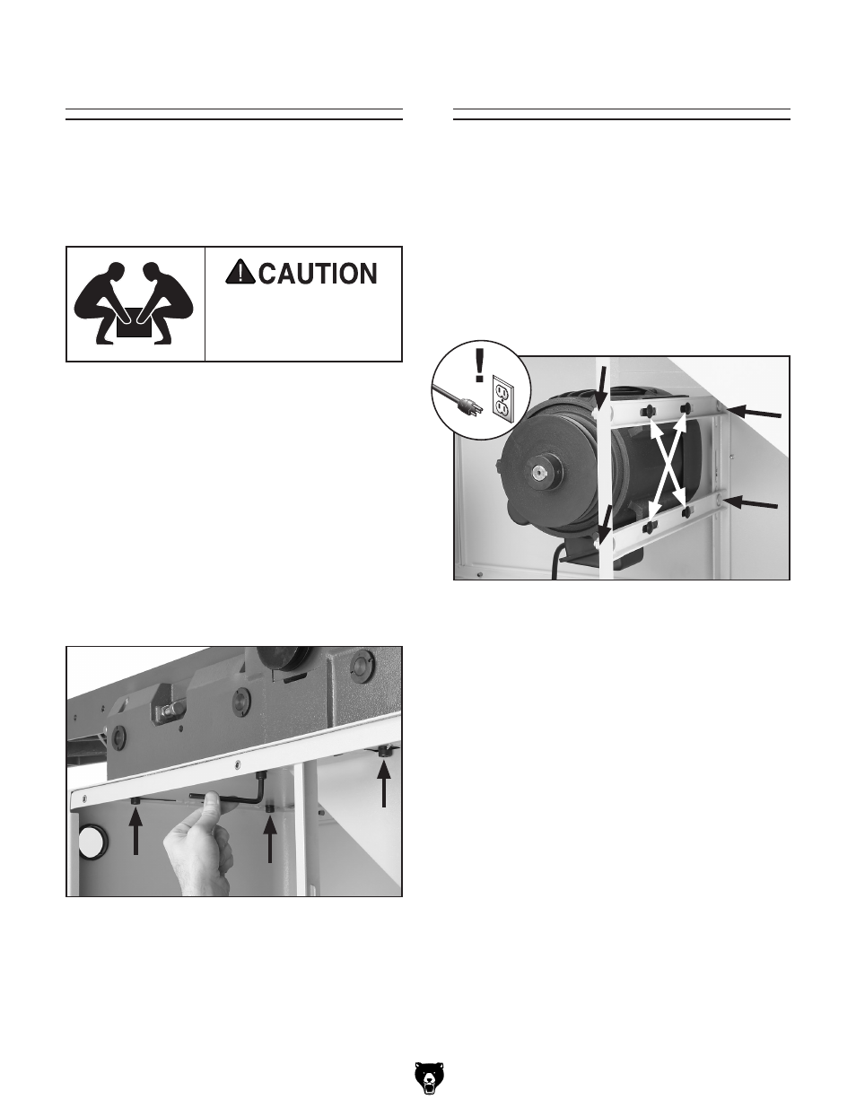
To install the V-belt:
1. Loosen the motor bracket fasteners shown in
Figure 7.
Jointer
V-Belt
2. Slide the motor upward and place the V-belt
around the cutterhead pulley and the motor
pulley.
3. Slide the motor down to tension the V-belt.
4. Visually check the alignment of the two pul-
leys to make sure that they are aligned and
that the V-belt is straight up and down (see
Figure 8).
— If the pulleys are aligned, tighten the motor
bracket fasteners and go to
Step 8.
— If the pulleys are NOT aligned, perform
Steps 5–7.
Figure 6. Securing jointer to stand.
Figure 7. Motor bracket fasteners (black arrows);
motor mount fasteners (white arrows).