Guardian Technologies 4758 User Manual
Page 64
SECTION 3.4
DIAGNOSTIC TESTS
TEST 23 - TEST TRANSFER RELAY TR
DISCUSSION:
In automatic operating mode, the transfer relay must
be energized by circuit board action or standby
source power will not be available to the standby
closing coil. Without standby source power, the
closing coil will remain de-energized and transfer to
"Standby" will not occur. This test will determine if the
transfer relay is functioning normally.
PROCEDURE:
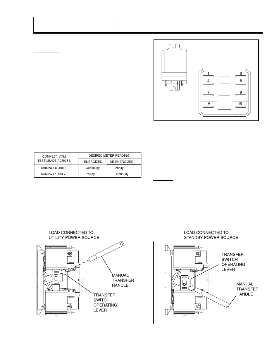
1. See Figure 2. Disconnect all wires from the transfer
relay, to prevent interaction.
2. Set a VOM to its "R x 1" scale and zero the meter.
3. Connect the VOM test leads across Relay Terminals 6
and 9 with the relay de-energized. The VOM should
read INFINITY.
4. Using jumper wires, connect the positive (+) post of a 12
volt battery to relay Terminal “A” and the negative (-)
battery post to Relay Terminal "B". The relay should
energize and the VOM should read CONTINUITY.
Figure 2. Transfer Relay Test Points
5. Now, connect the VOM test leads across Relay
Terminals 1 and 7.
a. Energize the relay and the meter should
indicate INFINITY.
b. De-energize the relay and the VOM should read
CONTINUITY.
RESULTS:
1. Replace transfer relay if it is defective.
2. If transfer relay checks good go to Test 26.
TEST 24- CHECK MANUAL TRANSFER
SWITCH OPERATION
V-TYPE PREPACKAGED
TRANSFER SWITCHES
PART 3
Page 3.4-3
Figure 3. Manual Transfer Switch Operation