2 antenna unit – Furuno FAR-2827 User Manual
Page 26
2. WIRING
2-2
2.2 Antenna
Unit
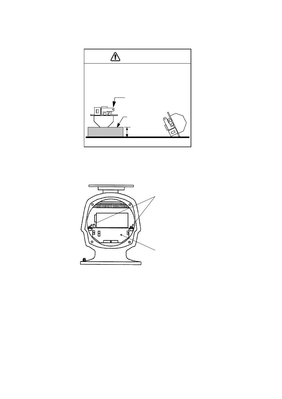
NOTE
Transceiver module
(magnetron inside)
Height more
than 5 cm
Non-ferrous
block
The magnetron in the transceiver module will de-
magnetize if it contacts ferrous material. When
dismounting the transceiver module, lay it on its
side or on top of non-ferrous material as shown
below.
1. Open the rear cover of the antenna unit
2. Disconnect plugs P823, P803, P831 and P921. If the PM-31 is installed, also disconnect
plug P911.
3. Unfasten two bolts and remove the transceiver module.
Fixing
bolts
Transceiver module
Antenna unit, rear view
4. Unfasten the four fixing bolts from the cable gland at the base of the antenna unit.
Remove clamping ring, rubber gasket and washers.
5. Pass the signal cable through the cable entry hole in the antenna unit mounting platform.
Trim the cable so about 80 cm of it protrudes past the cable gland.
- 2817-D (136 pages)
- 841 MARK-2 (58 pages)
- FAR-2157-BB (111 pages)
- UAIS TRANSPONDER FA-150 (4 pages)
- NAVNET 1763C (260 pages)
- FR-1710 (78 pages)
- FAR-2807 (52 pages)
- MARINERADAR FR-8062 (56 pages)
- 1935 (48 pages)
- FR-7062 (52 pages)
- FR-7252 (48 pages)
- COLOR VIDEO PLOTTER 1943C (251 pages)
- NAVPILOT 520 (73 pages)
- FAR-2167DS (111 pages)
- NAVpilot NAVpilot-500 (73 pages)
- NAVNET 1823C (260 pages)
- FR-2155 (89 pages)
- FA-100 (58 pages)
- NAVNET 1943 (248 pages)
- 1622 (24 pages)
- FR-2115/2125 (79 pages)
- 1942 MARK-2 (52 pages)
- 1942 MARK-2 (46 pages)
- 2137S (123 pages)
- 1832 (62 pages)
- 1832 (64 pages)
- 1832 (63 pages)
- FAR-2167DS-D (111 pages)
- 821 (64 pages)
- FR-8251 (69 pages)
- FR-2135S (82 pages)
- FAR-2127-BB (136 pages)
- NX-700A/B (89 pages)
- MSC.36(63) (1 page)
- IF-1500AIS (12 pages)
- FR-8051 (64 pages)
- FAR-2157 (111 pages)
- FAR-2157 (8 pages)
- 1712 (27 pages)
- UAIS TRANPONDER FA-150 (128 pages)
- FAR-2107(-BB) (312 pages)
- NATVET 1824C (239 pages)
- FAR-2107 (280 pages)
- NAVPILOT 500 (73 pages)