FUJITSU MAS3367 User Manual
Page 250
Sense Data Error Recovery Methods
5 - 16
C141-E167
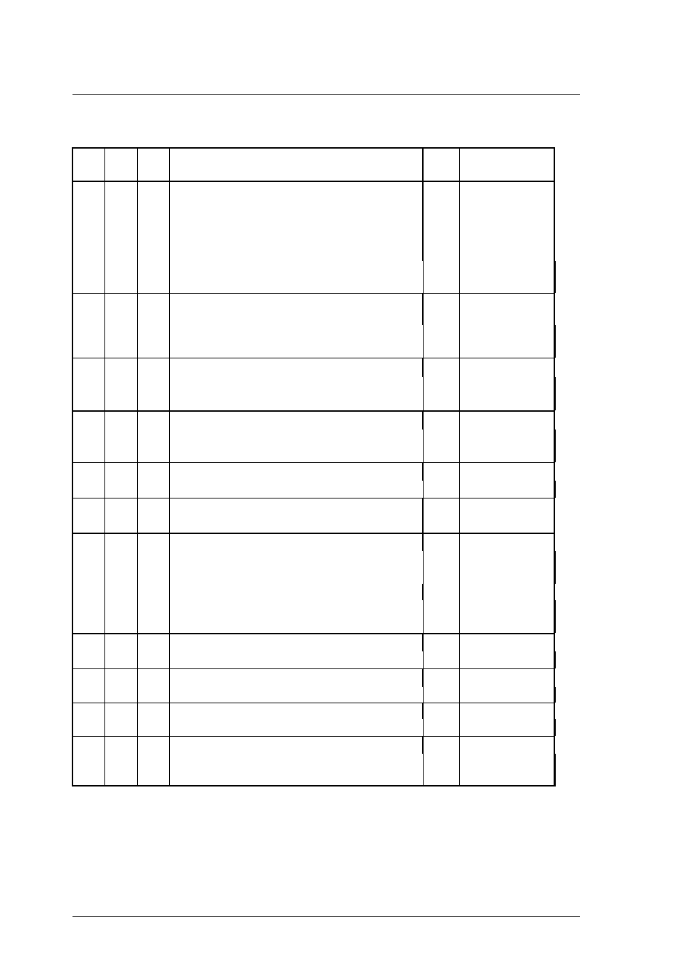
Table 5.3
Sense data error classification (3 of 4)
K*
C*
Q*
Outline of Error
L*
Recovery Method
(See Table 4.4.)
5
20
00
Invalid command operation code
None
2
21
00
Logical block address out of range
24
00
Invalid field in CDB
25
00
Logical unit not supported
26
00
Invalid field in parameter list
There is an error in the command specification
contents.
5
3D
00
Invalid bits in IDENTIFY message
None
3
90
00
Initiator's SCSI ID not identified
An error was detected in the SCSI protocol in the
command execution sequence.
6
29
xx
Power on, reset, or BUS DEVICE RESET occurred
None
14
The IDD was initialized by a Power on, RESET
condition or BUS DEVICE RESET message.
6
2A
01
Mode parameters changed
None
21
The MODE SELECT parameters were changed by
another INIT.
6
2F
00
Commands cleared by another INIT
None
25
Commands were cleared by another INIT.
6
3F
01
Microcode has been changed
None
27
02
Changed operation definition
6
5B
01
Log exception (Threshold condition met)
None
26
The current cumulative value exceeded the current
threshold value.
02
Log count at maximum
The current cumulative value reached the
maximum value.
6
5C
01
Spindle synchronized
None
22
Rotational synchronization was completed.
6
5C
02
Spindle not synchronized
None
23
Rotational synchronization deviated.
7
27
00
Write protected
None
15
Access to a read protected or write protected.
7
2C
00
Command sequence error
None
2
The SET LIMITS command was issued 2 times
within a group of commands linked in a series.
*
K: Sense Key
C: Sense Code
Q: Sub-sense code
L: Logging Necessary? (shown in Section 5.2.3)