2 logical address – FUJITSU MPE3XXXAE User Manual
Page 166
C141-E093-01EN
6 - 7
6.2.2
Logical address
(1)
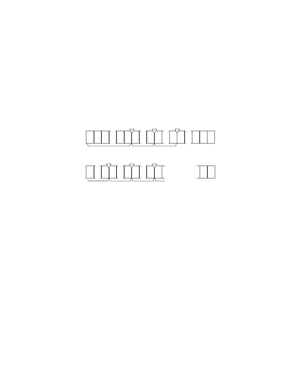
CHS mode
Logical address assignment starts from physical cylinder (PC) 0, physical head (PH) 0, and
physical sector (PS) 1 and is assigned by calculating the number of sectors per track which is
specified by the INITIALIZE DEVICE PARAMETERS command. The head address is
advanced at the subsequent sector from the last sector of the current physical head address.
The first physical sector of the subsequent physical sector is the consecutive logical sector
from the last sector of the current physical sector.
Figure 6.5 shows an example (assuming there is no track skew).
LS
63
LH2
LH1
LH0
LS
2
LS
1
LS
1
576
575
574
190
189
64
63
62
3
2
57
56
1
1
127
126
Physical sector
Physical sector
ex: Zone 0
Physical parameter
- Physical sector: 1 to 574 (For the rest, 2 spare sectors)
Specification of INITIALIZE DEVICE PARAMETERS command
- Logical head: LH=0 to 14
- Logical sector: LS=1 to 63
Physical cylinder 0
Physical head 1
Physical cylinder 0
Physical head 0
LS
63
LS
1
LS
63
LS
1
SP
SP
LS
7
. .
. .
. .
. .
. .
. .
. .
. .
LS
63
LS
8
LS
1
LS
63
LS
1
LS
63
LS
1
SP
SP
. .
. .
. .
. .
. .
. .
. . . .
. . . . . . . . . . . . . .
. . . . . . . . . . . . . .
LH11
LH10
LH12
LH13
120
183
182
119
576
575
Figure 6.5
Address translation (example in CHS mode)