FUJITSU MPE3XXXAE User Manual
Page 122
C141-E093-01EN
5 - 57
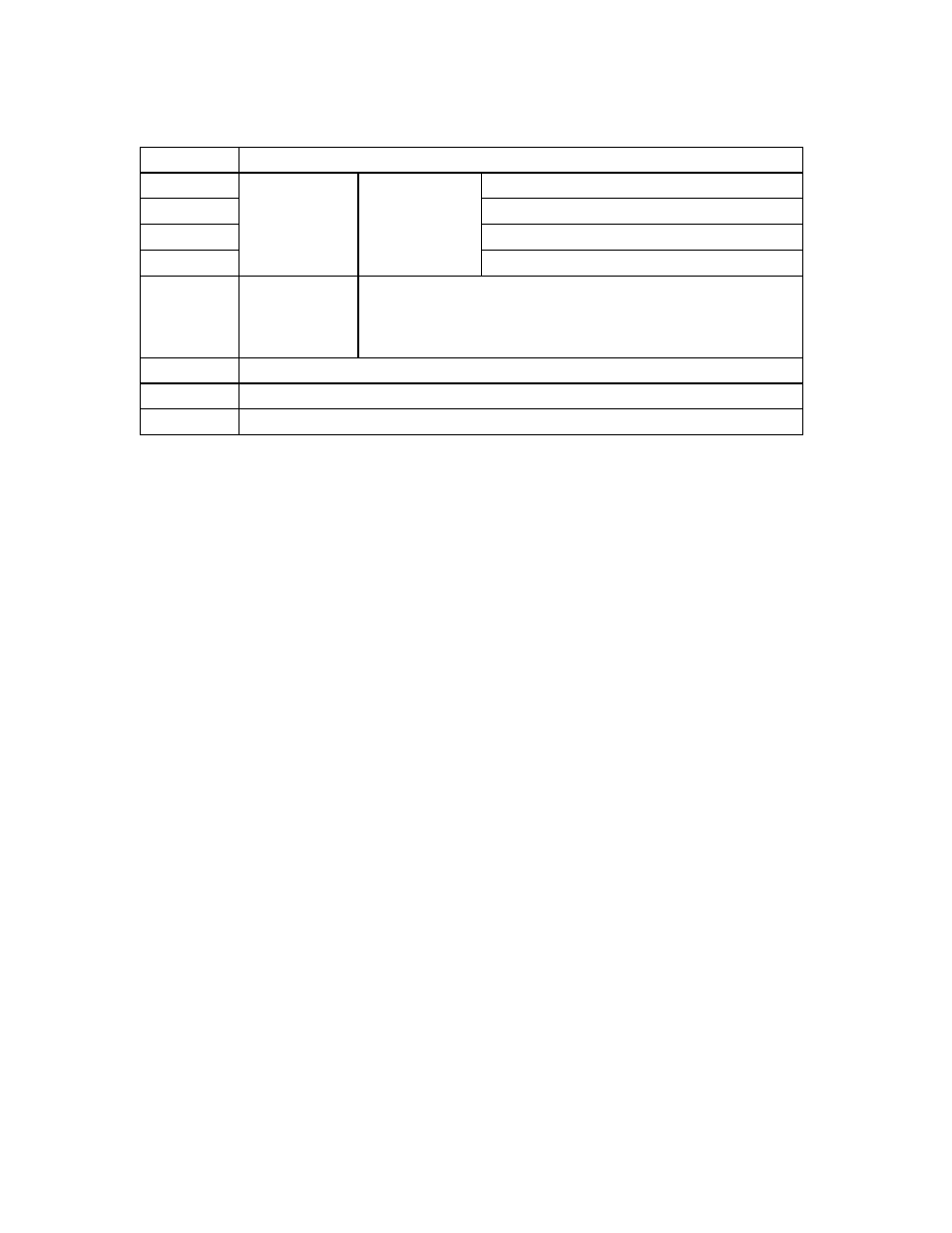
Table 5.11 SMART error log data format (2/2)
Byte
Item
45
Status register
46 to 58
Vendor Unique
59
State
5A, 5B
Total power on time [hour]
5C to 1C3
This format of each error log data structure is the same as Byte 02
to 5B.
1C4, 1C5
Drive Error Total Number
1C6 to 1FE
Reserved
1FF
Checksum
•
Error log index
Indicates the latest error log number. If an error has not occurred, 00 is displayed.
•
Error log 1 to 5
When an error occurs, the error log index value is incremented and information at the time
the error occurred is recorded in the error log area specified by this value. When the error
log index exceeds 05, it returns to 01.
•
Command data 1 to 5
Indicates five commands data in order received by the device until the error occurs.
Commands for which an error occurred are included in Command Data 5.
•
Error data
Indicates the I/O register values when the error is reported.
•
State
Bits 0 to 3: Indicates the drive status when received error commands according to the
following table.
Bits 4 to 7: Vendor unique
Error Log Data
Structure 1
Error Data
Structure
Error Log Data
Structure 2 to
Error Log Data
Structure 5