FUJITSU MPE3XXXAE User Manual
Page 121
C141-E093-01EN
5 - 56
•
Error logging capability
Bit 0:
Indicates that error logging function.
Bits 1 to 7: Reserved bits
•
Check sum
Two’s complement of the lower byte, obtained by adding 511-byte data one byte at a time
from the beginning.
•
Insurance failure threshold
The limit of a varying attribute value. The host compares the attribute values with the
thresholds to identify a failure.
If an unrecoverable error is detected during execution of a command received by the device
from the host computer, the device saves the SMART error log on the disk medium.
The host computer can issue the SMART Read Log Sector sub-command (FR register = D5h,
SN register = 01h) and read the SMART error log.
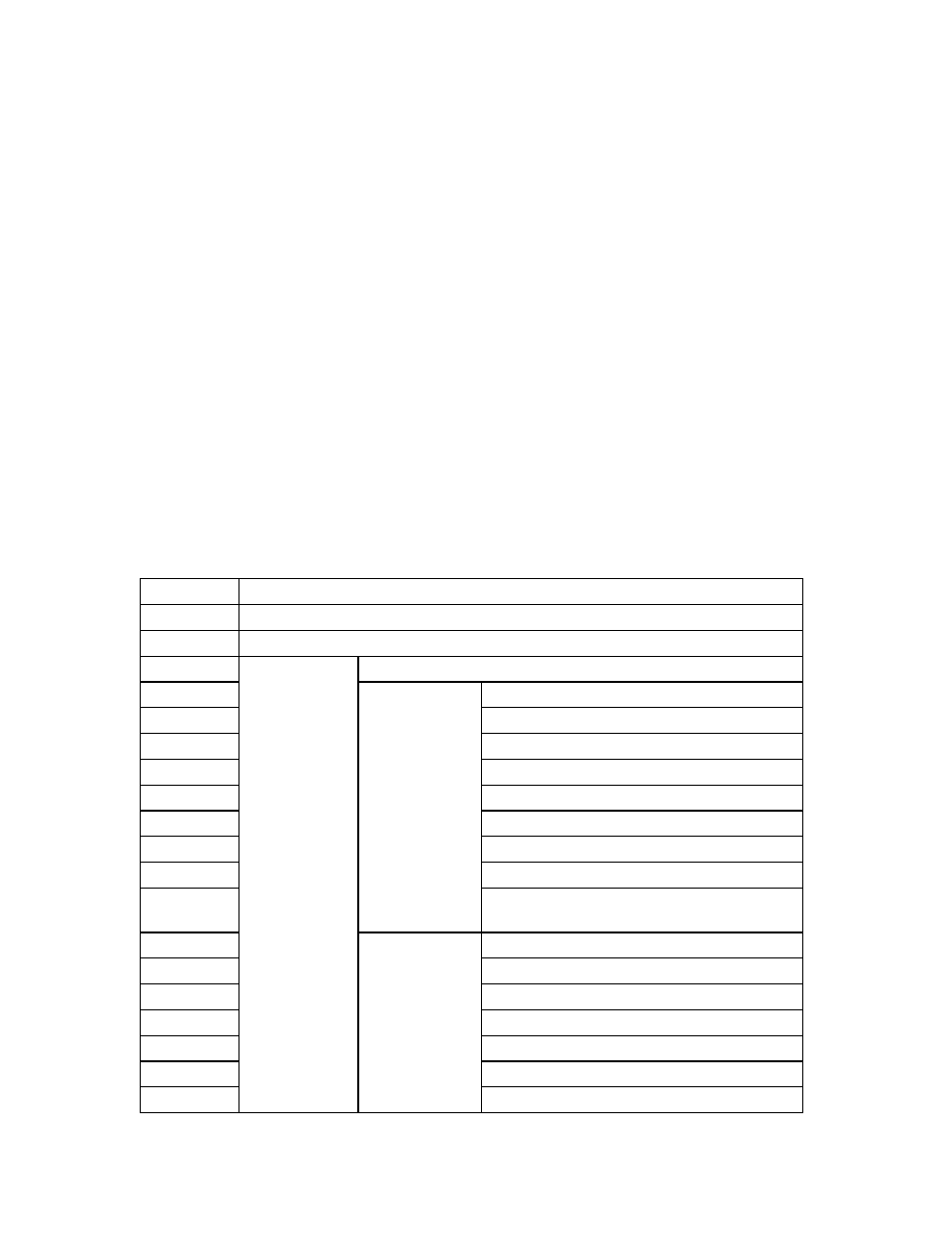
Table 5.11 SMART error log data format (1/2)
Byte
Item
00
Error log version number
01
The most recent “Error Log” point
02 to 31
Reserved
32
Device Control register
33
Features register
34
Sector Count register
35
Sector Number register
36
Cylinder Low register
37
Cylinder High register
38
Device/Head register
39
Command register
3A to 3D
Elapsed time [ms] from the point when the
power is turned on until command reception
3E
Reserved
3F
Error register
40
Sector Count register
41
Sector Number register
42
Cylinder Low register
43
Cylinder High register
44
Device/Head register
Error Log Data
Structure 1
Error Data
Structure
Command Data
Structure