Follett MCC400A/W User Manual
Page 25
25
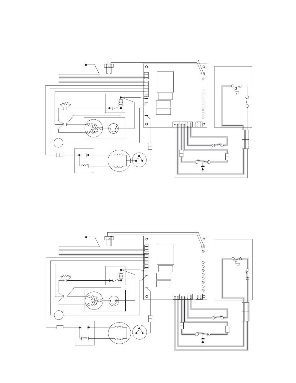
Normal operation – Stage 6
When the dwell time of 20 minutes has expired, the B-T LED goes off. The icemaker goes through the normal
start-up sequence when the bin level control signals the control board for ice. The WTR LED will remain on as
long as the water sensor in the float reservoir senses water.
Diagnostic sequence – Stage 7
The 20 minute error LED (20M) is on, indicating that the control board has sensed an over-torque condition
(above 2.5 AMPS on the gearmotor). The 20M LED remains on for 20 minutes after an over-torque condition has
occurred. The icemaker remains off as long as the 20M LED is on. When the 20M LED goes off, the control board
will try to go through a normal start-up sequence. The WTR LED remains on as long as the water sensor in the
float reservoir senses water.
RED
WTR
B-E
B-T
2ND
60M
20M
C
POWER
DR
WHITE
BLACK
YELLOW
WHITE
4
3
2
T.O.L.
START
RUN
GEARMOTOR
COMPRESSOR
R
POTENTIAL
START RELAY
RUN
CAP.
CAPACITOR
START
C
S
2
1
5
T.O.L.
L1
L2
COMP
FAN
DRV
WATER
SENSOR
G
GREEN/YELLOW
GRN IN
ELEC BOX
BROWN
BLUE
WHITE
WHITE
BLACK
BLACK
ORANGE
RED
BLACK
BLACK
BLACK
BLACK
VIOLET
VIOLET
WHITE
BLACK
RED
RED
BLUE
BLACK
FAN
M
ORANGE
BLACK
L
N
HIGH PRESSURE
SAFETY SWITCH
COMPRESSOR
SWITCH
BIN
T-STAT
BIN
SIGNAL
SWITCH
DISPENSER
RED
WTR
B-E
B-T
2ND
60M
20M
C
POWER
DR
WHITE
BLACK
YELLOW
WHITE
4
3
2
T.O.L.
START
RUN
GEARMOTOR
COMPRESSOR
R
POTENTIAL
START RELAY
RUN
CAP.
CAPACITOR
START
C
S
2
1
5
T.O.L.
L1
L2
COMP
FAN
DRV
WATER
SENSOR
G
GREEN/YELLOW
GRN IN
ELEC BOX
BROWN
BLUE
WHITE
WHITE
BLACK
BLACK
ORANGE
RED
BLACK
BLACK
BLACK
BLACK
VIOLET
VIOLET
WHITE
BLACK
RED
RED
BLUE
BLACK
FAN
M
ORANGE
BLACK
L
N
HIGH PRESSURE
SAFETY SWITCH
COMPRESSOR
SWITCH
BIN
T-STAT
BIN
SIGNAL
SWITCH
DISPENSER