Follett MCC400A/W User Manual
Page 24
Normal operation – Stage 4
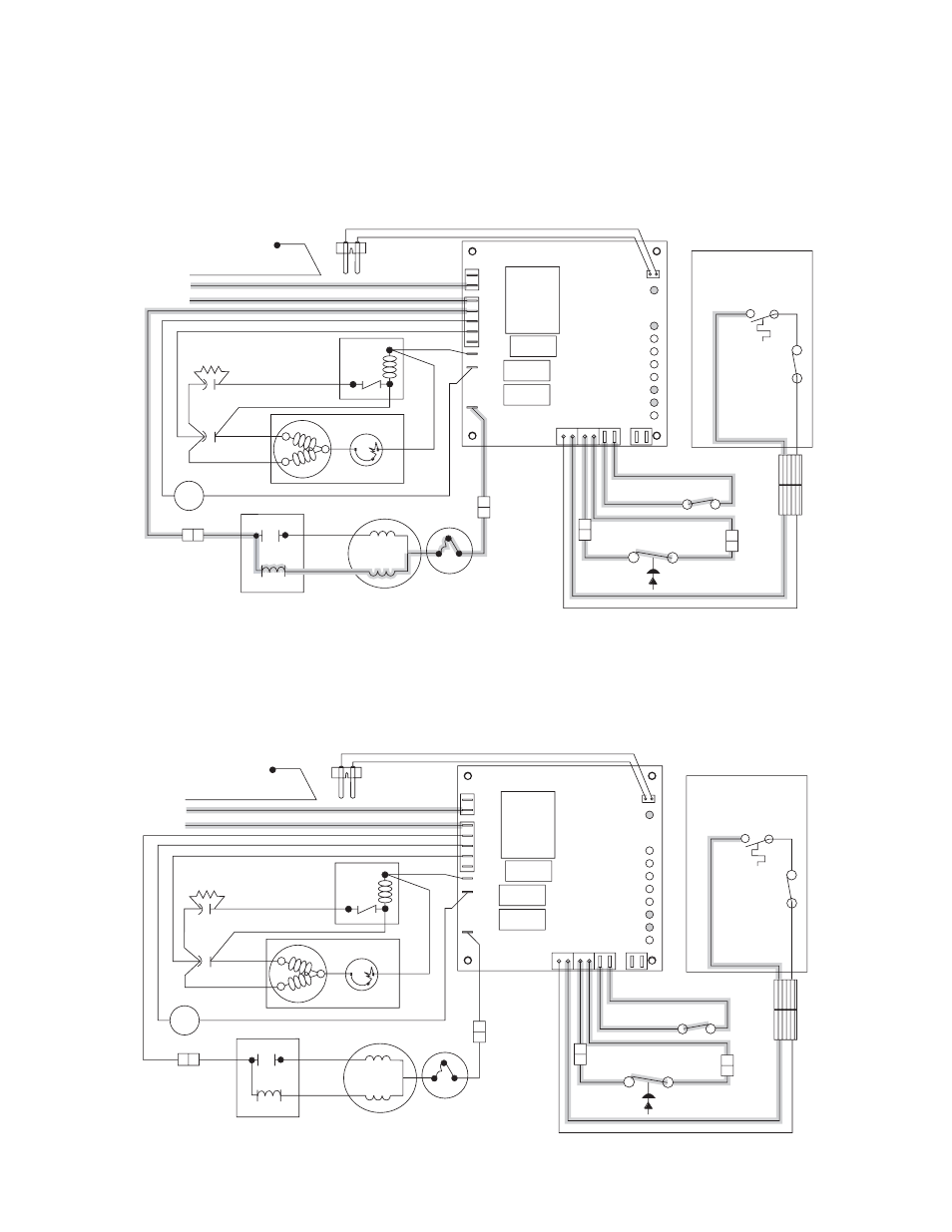
Once the ice level control opens, the B-E LED goes out. After a 10 second delay the compressor LED (C),
compressor and fan motor go off. (Should the ice level control not remain open for 10 seconds, the icemaker
will continue to run.) The gearmotor continues to run and the DR LED remains on for 60 seconds. The purpose
of this function is to drive the remaining ice out of the evaporator and to boil off any refrigerant remaining in the
evaporator. The bin timer LED (BT) comes on, starting the twenty minute off cycle time delay.
24
Normal operation – Stage 5
The drive motor now shuts down and the DR LED is off. The B-T LED remains on for 20 minutes. The icemaker
will not start while the B-T LED is on. To restart the icemaker for troubleshooting purposes, depress the reset
button to clear the control board.
RED
WTR
B-E
B-T
2ND
60M
20M
C
POWER
DR
WHITE
BLACK
YELLOW
WHITE
4
3
2
T.O.L.
START
RUN
GEARMOTOR
COMPRESSOR
R
POTENTIAL
START RELAY
RUN
CAP.
CAPACITOR
START
C
S
2
1
5
T.O.L.
L1
L2
COMP
FAN
DRV
WATER
SENSOR
G
GREEN/YELLOW
GRN IN
ELEC BOX
BROWN
BLUE
WHITE
WHITE
BLACK
BLACK
ORANGE
RED
BLACK
BLACK
BLACK
BLACK
VIOLET
VIOLET
WHITE
BLACK
RED
RED
BLUE
BLACK
FAN
M
ORANGE
BLACK
L
N
HIGH PRESSURE
SAFETY SWITCH
COMPRESSOR
SWITCH
BIN
T-STAT
BIN
SIGNAL
SWITCH
DISPENSER
RED
WTR
B-E
B-T
2ND
60M
20M
C
POWER
DR
WHITE
BLACK
YELLOW
WHITE
4
3
2
T.O.L.
START
RUN
GEARMOTOR
COMPRESSOR
R
POTENTIAL
START RELAY
RUN
CAP.
CAPACITOR
START
C
S
2
1
5
T.O.L.
L1
L2
COMP
FAN
DRV
WATER
SENSOR
G
GREEN/YELLOW
GRN IN
ELEC BOX
BROWN
BLUE
WHITE
WHITE
BLACK
BLACK
ORANGE
RED
BLACK
BLACK
BLACK
BLACK
VIOLET
VIOLET
WHITE
BLACK
RED
RED
BLUE
BLACK
FAN
M
ORANGE
BLACK
L
N
HIGH PRESSURE
SAFETY SWITCH
COMPRESSOR
SWITCH
BIN
T-STAT
BIN
SIGNAL
SWITCH
DISPENSER