Field wiring diagrams – Follett MCC400A/W User Manual
Page 10
DISPENSER
Left junction box
GND
GRN
B
W
Right junction box
BL
Y
RD
W
B
Lower junction box
(24V bin signal)
Icemaker #2
(optional)
W
B
X
GND
GRN
B
W
Lower junction box
(24V bin signal)
Icemaker #1
(optional)
Upper junction box
(power)
X
GND
GRN
B
W
Upper junction box
(power)
LEGEND
X
EQUIPMENT
GROUND
WIRENUT FIELD
CONNECTIONS
B
BLACK
W
WHITE
GRN
GREEN
BL
BLUE
Y
YELLOW
RD
RED
X
GND
GRN
W
B
W
R
Lower icemaker
junction box
(bin signal)
B
Dispenser
junction box
X
W
GND GRN
Upper icemaker
junction box
(power)
B
Electric
power
source
Electric
power
source
Electric
power
source
Electric
power
source
Electric
power
source
10
Recommended junction box preparation of
hard-wired Satellite-fill icemakers.
1. Replace upper (power) strain relief with
a
cord
connector.
2. Mount two 51mm x 102mm (2" x 4")
junction boxes using supplied holes in
icemaker
face.
3. Make power and bin signal connections.
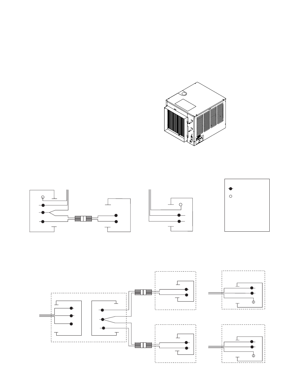
Field wiring diagrams
Field wiring diagram is intended only to aid electrician or technician in understanding how equipment works.
Should local codes require a hard-wired connection and/or shielded wiring, eliminate the cord and plug(s) and
follow the appropriate field wiring diagram.
MCC400A/W and C/ER400A/W icemakers have separate power supply from dispenser
Electric disconnects required within 3m (10 ft) for all hard-wired connections
25, 50 or 110 ice and water dispenser with ONE Satellite-fill icemaker
VU155/VU300 ice and beverage dispenser with either ONE or TWO autofill icemaker kits