Fluke 1744 User Manual
Page 33
1744/1743
Users Manual
24
1. Connect the voltage test leads to the outputs of the voltage
transformers (VTs).
2. In PQ Log, select the measuring range with P-N logging and
matching nominal voltage.
3. Enter the correct converter/transformer ratio for current and voltage.
Note
Current clamp sets are available for 1 A current transformers.
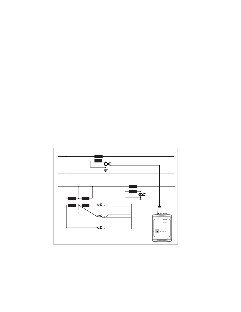
Logging with Two Voltage Converters and Two Current
Transformers
In 3-phase 3-wire systems with two voltage converters (VTs) and two current
transformers (CTs) in an Aron or Blondel measuring circuit, the Logger can
measure only phase-phase (P-P, Delta).
L1
L2, N
L1
L3
L2
L3
POWER LOGGER
1743
START
STOP
POWER
2
3
2
S
R
IN I3 I2 I1 V3 V2 V1
CURRENT INPUT
10 VRMS MAX
L1/A
L2/B
L3/C
N
5 VA
45 -65 Hz
MEASUREMENT INPUT
SUPPLY INPUT
830 VRMS MAX CAT
600 V CAT
300 V CAT
100 -350 V
660 V MAX
88 -660 V
egb009.eps
Figure 10. Measuring 3-Phase Voltages in a 3-Wire System with Potential
Transformers (Aron Measuring Circuit)
Test Equipment Depot - 800.517.8431 - 99 Washington Street Melrose, MA 02176
FAX 781.665.0780 - TestEquipmentDepot.com